Add2-dvi-dual, Connector description – Kontron 820958 ADD2-DVI-Dual-Internal-150 User Manual
Page 8
ADD2-DVI-Dual
KTD-00714-F
Public User Manual
Date: 2008-11-25
Page
8 of 9
Connector Description
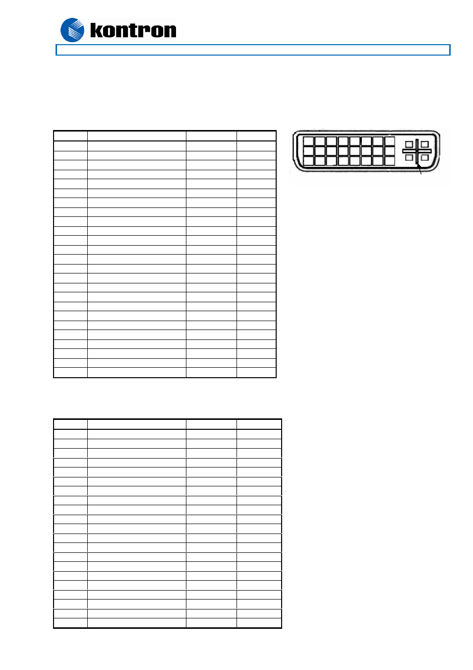
The DVI-I connector is a Molex 74320-1004 (or similar). Only DVI Digital output is supported.
(Both DVI-I and DVI-D cables can be connected).
The DVI-SIL, is a Hirose DF19G-20P-1H. Mating connector is Hirose DF19L-20P-1H or similar.
Pin No.
Signal
Type
Pull Up
1
TMDS Data 2-
LVDS OUT
2
TMDS Data 2+
LVDS OUT
3
TMDS Data 2/4 Shield
PWR
4 N.C.
-
5 N.C.
-
6 DDC
Clock IO
2K2
7 DDC
Data IO
2K2
8 N.C.
-
9
TMDS Data 1-
LVDS OUT
10
TMDS Data 1+
LVDS OUT
11
TMDS Data 1/3 Shield
PWR
12 N.C.
-
13 N.C.
-
14 +5V
(55mA) PWR
15 GND PWR
16
Hot Plug Detect
I
17
TMDS Data 0-
LVDS OUT
18
TMDS Data 0+
LVDS OUT
19
TMDS Data 0/5 Shield
PWR
20 N.C.
-
21 N.C.
-
22
TMDS Clock Shield
PWR
23
TMDS Clock+
LVDS OUT
24
TMDS Clock-
LVDS OUT
C1 - C5
N.C.
-
Pin No.
Signal
Type
Pull Up
1 GND PWR
2 GND PWR
3 +5V
(55mA) PWR
4
Hot Plug Detect
I
5 GND PWR
6 DDC
Data IO
2K2
7 DDC
Clock IO
2K2
8 GND PWR
9
TMDS Clock-
LVDS OUT
10
TMDS Clock+
LVDS OUT
11 GND PWR
12
TMDS Data 0-
LVDS OUT
13
TMDS Data 0+
LVDS OUT
14 GND PWR
15
TMDS Data 1-
LVDS OUT
16
TMDS Data 1+
LVDS OUT
17 GND PWR
18
TMDS Data 2-
LVDS OUT
19
TMDS Data 2+
LVDS OUT
20 GND PWR
Shield GND
PWR
1 8
9 16
17 24
C1 C2
C3 C4
C5
Front view