2 sfp, 3 sfp, 4 qsfp – Kontron RTM8940 User Manual
Page 20: 5 e1 - t1 bits, 2 sfp 2.3 sfp+ 2.4 qsfp+ 2.5 e1 - t1 bits
7
www.kontron.com
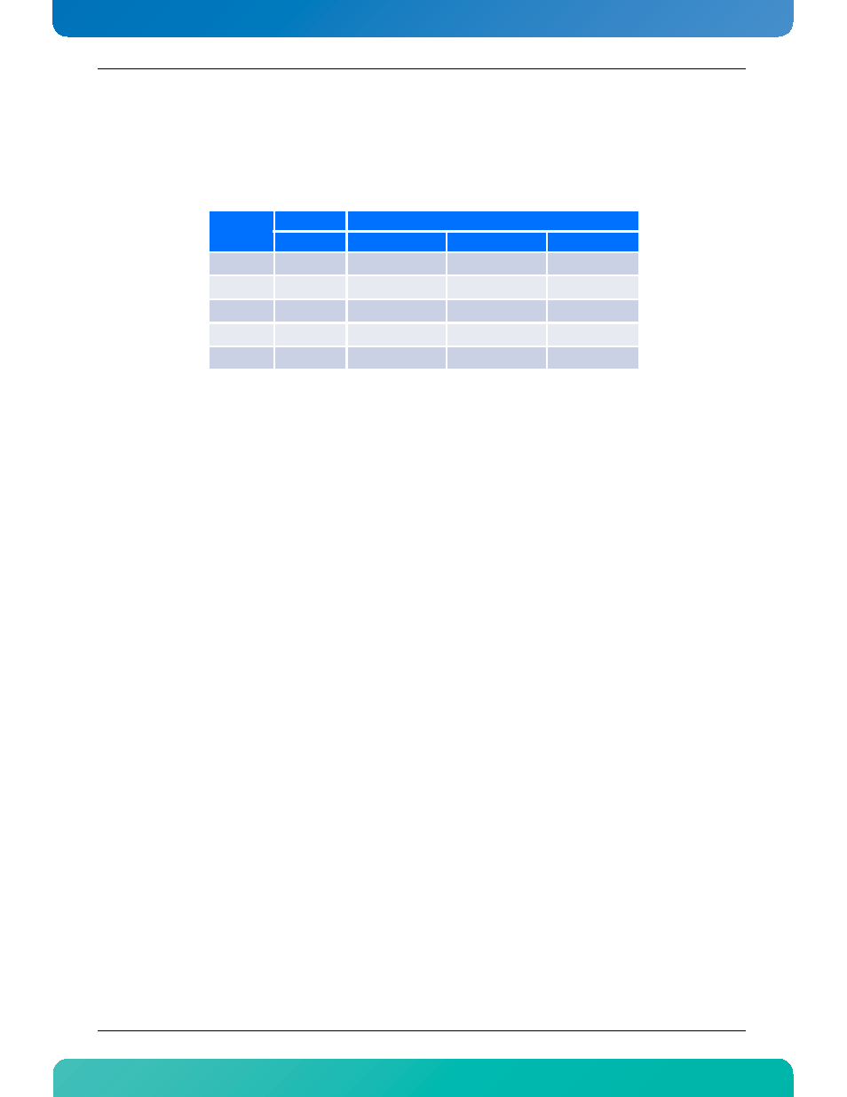
The configuration of the RTM8940 supports enabling up to 2 out of the following 3 sets of ports
simultaneously: RTM 4x SFP+, RTM QSFP+(#1) and RTM QSFP+(#2).
See the table below for the possible configuration with the AT8940:
Table 2-1:Possible Ports Mappings: AT8940 with RTM8940
NOTE:
• Port configurations will be set by using the cli command: set board port-map Port-Map-number
• Configurations 1 and 2 are for a 6 and 14-slot ATCA chassis
• Configurations 3-4-5 are for a 16-slot ATCA chassis
For the AT8910 the fixed configurations is 4x Front SFP+ ports on 0/1-0/4 and 4x RTM SFP+ ports on 0/20-0/
23. QSFP+ ports are not supported by the RTM8940 when used with the AT8910.
2.2
SFP
The RTM8940 has one dual SFP module connector available on the RTM face plate. The SFP module signals are
coming from the front board at 1Gb through zone 3 connector.
2.3
SFP+
The RTM8940 has two dual SFP+ module connectors available on the RTM face plate. The SFP+ module signals
are coming from the front board at 10G through zone 3 connector.
2.4
QSFP+
The RTM8940 has two QSFP module connectors available on the RTM face plate. The QSFP module signals are
coming from the front board at 40Gb through zone 3 connector.
2.5
E1 - T1 BITS
The RTM8940 has four E1 - T1 BITS connectors available on the RTM face plate. The clock signals are coming
from the front board or from an external source. It supports:
Port- MAP-
Number
Front
RTM
4x SFP+
4x SFP+
QSFP+(#1)
QSFP+(#2)
1
0/1-0/4
0/19-0/22
0/18
Disabled
2
0/1-0/4
Disabled
0/18
0/19
3
0/1-0/4
Disabled
Disabled
Disabled
4
0/1-0/4
0/20-0/23
0/19
Disabled
5
0/1-0/4
Disabled
0/19
0/20