Just Better Deep Vacuum Pump Cartridge User Manual
Page 2
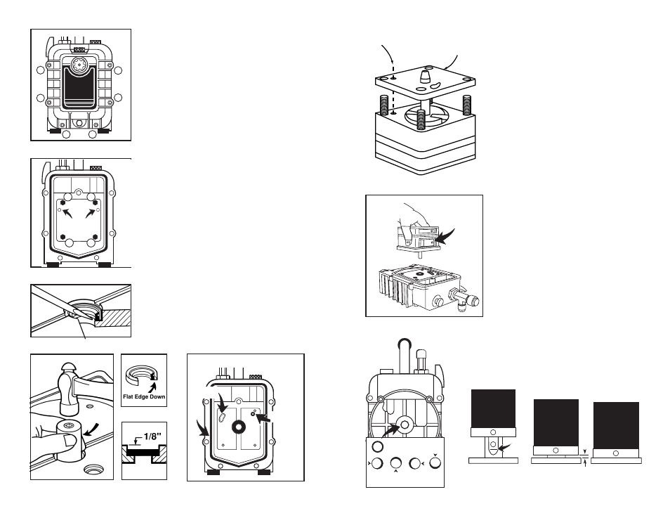
FIG. 4
FIG. 5
FIG. 6
FIG. 7
REMOVING OIL COVER
1. Using 3/16" Allen wrench remove
6 socket head cap screws from
oil cover. (FIG. 4)
REMOVING CARTRIDGE
1. Remove 4 cartridge screws (7/16"
or 3/8" wrench) (FIG. 5). Discard
old gasket seal and 2 O-rings
along with cartridge and bolts.
REPLACING SHAFT SEAL
AND O-RINGS
1. Insert screwdriver blade under
shaft seal and pry the seal from
the housing being careful not to
damage the walls or face of the
trap. (FIG. 6)
2. With clean rag remove all oil and
residue from inside hole and front
and back of trap.
3. Lay trap on flat surface with
handle toward you. Press new
shaft seal with flat side down into
opening by hand. To seat, tap
seal with 11/16" socket. Seal is
properly seated 1/8" down from
top edge (FIG. 7). Apply vaseline
or grease to inside edges of seal.
4. Insert intake and gas ballast
O-rings in trap (FIG. 8). Gasket
replaced after cartridge is
installed.
REPLACING
PUMP CARTRIDGE
Read section carefully before at-
tempting replacement.
1. Keep trap flat on bench. Remove
holding nuts from cartridge,
keeping all parts in alignment.
(Four nuts can be discarded.)
Cartridge is held with shaft down
and flutter valves facing intake fit-
ting. Center shaft with seal open-
ing. (FIG. 9) Align with threaded
holes and place in position. Hand
tighten four bolts. Cross tighten
with 7/16" wrench.
2. Check alignment by rotating shaft
with coupler. If shaft moves freely
continue assembly. If shaft binds,
loosen bolts and turn shaft until
shaft rotates freely. Retighten
bolts. Shaft should be concentric
with shaft hole when viewed from
backside. (FIG. 10)
3. Replace gasket (FIG. 8) and re-
install oil cover to trap. (FIG. 4)
4. Remove setscrews on coupler.
Coat setscrew threads with
thread sealant. Re-install cou-
pling to pump cartridge with set
screw facing flat side of shaft .
Tighten screw so coupler slides
on shaft but stops at bottom of
flat. Tighten until screw head is
flush with coupler. Coupler should
be approximately 1/8" off trap
surface. (FIG. 11)
FIG. 9
FIG. 10
FIG. 8
FIG. 11 (Coupler styles may vary from illustration.)
1/8"
Bottom
Of Flat
Bottom of Flat Correct Incorrect
OIL LEVEL
1
2
3
4
5
6
Cover
Seal
Intake
O-Ring
Gas Ballast
O-Ring
Do not disturb
hex setting
screws
1
2
4
3
Shaft Aligned
Correctly
Shaft Touching Edge
Of Trap Hole
Align
Gas Ballast
Holes
If new intake plate on
cartridge differs from the
old intake plate use the old
intake plate.
Intake
Valve
11/16"
socket