4wd movement board test, Tb 1, Tb 2 – Dynojet 424 Linx: 4WD Dyno Air and Wiring Schematic User Manual
Page 2
D
YN
O
JE
T
R
E
SE
A
R
C
H
,
IN
C
0
3
/1
6
/0
0
TB
2
RA
IL
OU
T
IN
BR
K 2
BR
K 1
BRK IN +12V
C
O
M
PRES
----
G
N
D
IN OUT
SW
TB
1
4WD Movement
65412001
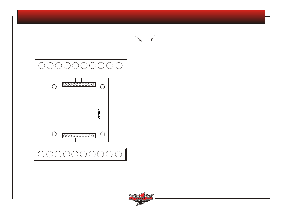
Use a multi-meter to read each terminal and determine the voltage that
should be present as listed on this sheet.
The red probe is always placed on the first number.
TB2: Top Row of Terminals on PCB
Reading Left to Right
TB1: Bottom Row of Terminals on PCB
Reading Left to Right
1—2
brake signal from Breakout board
brake off
+12 VDC
brake on
0 VDC
3—4
12 VDC in from P/S
5—4
when brake is applied, reads 12 VDC
6—4
with brake applied, with the remote switch pressed to IN, reads 12 VDC
7—4
with brake applied, with the remote switch pressed to OUT, reads 12 VDC
8—
not wired
For this test, you will check for continuity:
9—10 air pressure switch: sufficient air pressure equals continuity, insufficient air
pressure equals no continuity
10—9 brake signal to cable
brake off
+12 VDC
brake on
0 VDC
8—7
brake signal to solenoid
brake off
+12 VDC
brake on
0 VDC
6—5
11.57 VDC when IN switch on remote is pushed
4—3
11.57 VDC when OUT switch on remote is pushed
2—1
10.68 VDC when either IN/OUT switch is pushed on remote
T
B
1
1
2
3
4
5
6
7
8
9
10
TB
2
10
9
8
7
6
5
4
3
2
1
red probe
on first
number
black
probe
For assistance, call Dynojet Technical Support at 1-800-992-3525, visit www.dynojet.com, or write to Dynojet at 2191 Mendenhall Drive, North Las Vegas, NV 89031.
98225108 • Version 1 • Page 2 of 2
© Copyright 2004 Dynojet Research, Inc. All Rights Reserved. 02/2004SD
4WD MOVEMENT BOARD TEST