Installation – Dynojet 250: Safety Switch User Manual
Page 3
Installation
1) Remove the cover on the wire junction box.
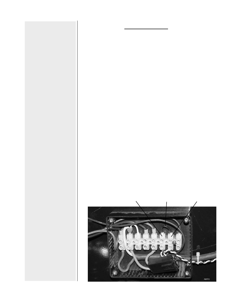
2) Loosen the set screws that hold the jumper wire, and
then remove the jumper wire.
3) Feed the yellow and black wires that are attached to the
safety switch through the grommet hole on the right rear
side of the dyno.
4) Feed the yellow and black wires through side of the wire
junction box.
5) The wires from the switch are to be installed across where
the jumper lead was removed. Wire so the yellow from
the switch lines up with the yellow lead on the bottom of
the terminal strip. Wire the black lead from the switch so
that it lines up the black wire on the bottom of the terminal
strip.
6) The safety switch needs to be mounted at the entry of the
dyno cell. The switch is “open” when the plunger is out,
and “closed” when the plunger is depressed. Mount the
switch on the dyno cell door / access gate so that the
switch is closed when the door is closed. When the door
is opened, the switch will “open” and the the dynamometer
will stop running.
black lead
yellow lead
remove
jumper