Wiring diagram, Wiring instructions, Installation and mounting instructions: cont – Code 3 SuperVisor with Torus User Manual
Page 3: Warning! led fusing considerations, Warning
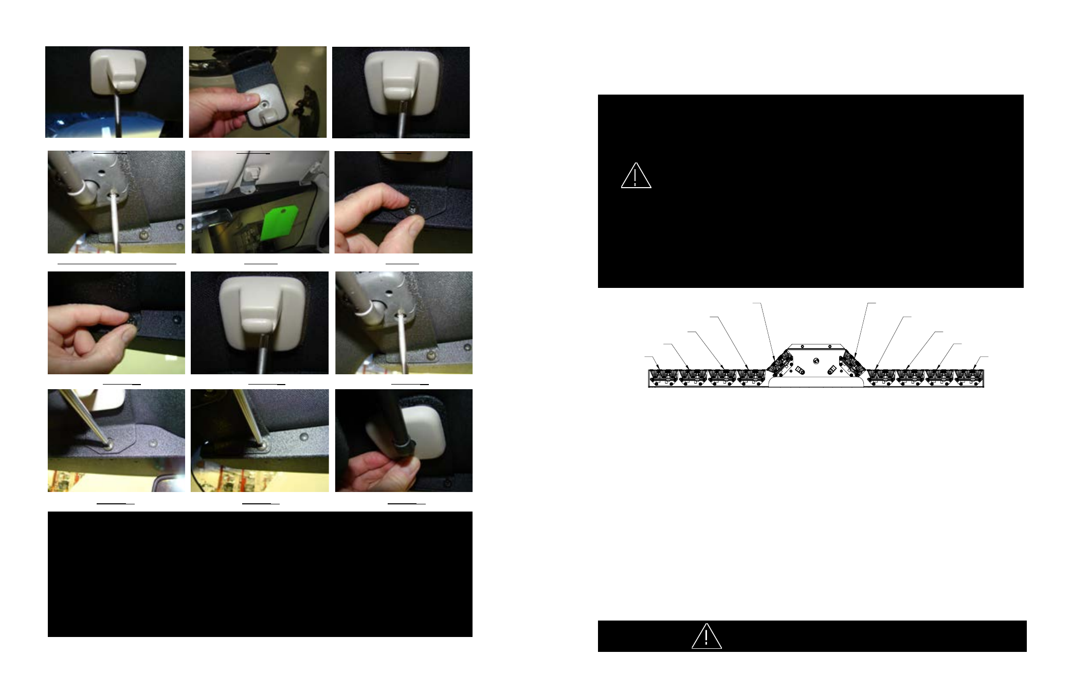
PASSENGER
SIDE
DRIVER
SIDE
LT BLUE
PURPLE
WHITE
RED
ORANGE
GREEN/WHT
RED/WHITE
PINK
BROWN
BLACK----------NEGATIVE GROUND
BLUE/WHT---------NOT USED
GREEN------------NOT USED
YELLOW-----------NOT USED
FUSE SIZE CALCULATION:
USE .5 AMP FOR EACH LED HEAD
WIRING DIAGRAM
BROWN/WHT
5
4
Larger wires and tight connections will provide longer service life for components. For high current wires it
is highly recommended that terminal blocks or soldered connections be used with shrink tubing to protect
the connections. Do not use insulation displacement connectors (e.g. 3M
®
Scotchlock type connectors).
Route wiring using grommets and sealant when passing through compartment walls. Minimize the
number of splices to reduce voltage drop. High ambient temperatures (e.g. under hood) will significantly
reduce the current carrying capacity of wires, fuses, and circuit breakers. Use "SXL" type wire in engine
compartment. All wiring should conform to the minimum wire size and other recommendations of the
manufacturer and be protected from moving parts and hot surfaces. Looms, grommets, cable ties, and
similar installation hardware should be used to anchor and protect all wiring. Fuses or circuit breakers
should be located as close to the power takeoff points as possible and properly sized to protect the wiring
and devices. Particular attention should be paid to the location and method of making electrical connections
and splices to protect these points from corrosion and loss of conductivity. Ground terminations should
only be made to substantial chassis components, preferably directly to the vehicle battery. The user should
install a fuse sized to approximately 125% of the maximum Amp capacity in the supply line to protect
against short circuits. For example, a 30 Amp fuse should carry a maximum of 24 Amps. DO NOT USE
1/4" DIAMETER GLASS FUSES AS THEY ARE NOT SUITABLE FOR CONTINUOUS DUTY IN SIZES
ABOVE 15 AMPS. Circuit breakers are very sensitive to high temperatures and will "false trip" when
mounted in hot environments or operated close to their capacity.
wARNINg!
LED Fusing Considerations
Although the average current draw per module is very low, due to the type of circuit used to power each module, the instan-
taneous peak current to a module can be significantly higher during low voltage conditions. To avoid prematurely blowing
ATO style fuses or tripping breakers it is recommended the following rule-of-thumb be used to size fuses or breakers. This is
especially important in lightbars with many LED modules running off a single fused source.
Minimum fuse size calculation: (See wiring Diagram page 5)
For LED 12 volt electrical current only
.5 X (number of 3 LED modules being fused) = Total Electrical Current at 12.8 VDC
This Product contains high intensity LED devices. To prevent eye damage,
DO NOT stare into light beam at close range.
wARNINg!
wiring Instructions
Finish routing the cable as desired. It is advisable to leave an extra loop of cable when installing the light bar to allow for future
changes or reinstallations. Connect the black lead to a solid frame ground (earth), preferably the (-) or ground (earth) side of the
battery, and the power wire to the +12V terminal of the battery. Connect the remaining wires as shown on page 5.
Caution: Drilling into the housing of the light bar could damage wiring or other internal components.
FIgURE
10
FIgURE
11
FIgURE
12
FIgURE
13
FIgURE
14
FIgURE
15
FIgURE
7-DRIVER SIDE SHOwN
FIgURE
8
FIgURE
9
Installation and Mounting Instructions: Cont.
wARNINg: This unit must be mounted within the interior passenger compartment of the vehicle only. It is not intended
for use in exterior applications. All devices should be mounted in accordance with the manufacturer’s instructions
and securely fastened to vehicle elements of sufficient strength to withstand the forces applied to the device.
Driver and/or passenger air bags (SRS) will affect the way equipment should be mounted. This device should be
mounted by permanent installation and within the zones specified by the vehicle manufacturer, if any. Any device
mounted in the deployment area of an air bag will damage or reduce the effectiveness of the air bag and may damage
or dislodge the device. Installer must be sure that this device, its mounting hardware and electrical supply wiring does
not interfere with the air bag or the SRS wiring or sensors. Mounting the unit inside the vehicle by a method other
than permanent installation is not recommended as unit may become dislodged during swerving, sudden braking or
collision. Failure to follow instructions can result in personal injury.
FIgURE
4
FIgURE
5
FIgURE
6