Code 3 PSE LED 12 Output Flashers User Manual
Page 2
2
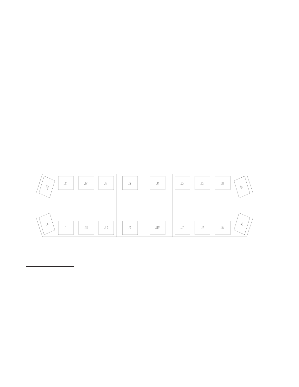
Output Designation:
J4,J5
: PS Front
J6
: PS Rear Corner
J2,J3
: DS Front
J1
: DS Rear Corner
J7,J12 : PS Rear
J8
: PS Front Corner
J9,J10 : DS Rear
J11
: DS Front Corner
Lightbar Configurations:
When using this product as a lightbar Flasher, the Flasher outputs should be connected as follows (refer
to Fig.2):
Figure2
Lightbar Installation:
(Refer to Figure 3 and 4)
1.) Plug the Control Harness into the Flasher.
2.) Connect the +12V and ground wires to quickslide terminals E1 & E2 respectively. Use 14Ga. wire
for the main +12V and ground connections.
Note: GND, terminal E2 can be grounded to the lightbar frame. Ensure that the power wire is
fused with a 15 Amp AUTO style fuse.
3.) Connect the white(Mode1), red/blk(Mode2), and red(Mode3) wires to three 18Ga. wires on the
lightbar cable harness. Ensure that wire colors are marked on the lightbar wire-tag sheet.
4.) Connect the yellow(Flash Pattern PGM) wire to an 18 Ga. wire on the lightbar cable harness.
Ensure that the chosen wire color is marked on the lightbar wire-tag sheet. The PGM wire can
then be connected to a momentary +12V switch and used to program the desired flash pattern for
any of the lightbar's three operating modes.
5.) Connect the green(Front Cutoff) and blue(Rear Cutoff) wires to two 18Ga. wires on the lightbar
cable harness. Ensure that the chosen wire colors are marked on the lightbar wire-tag sheet.
Available Versions:
This product is available in two different versions:
1. Lightbar Flasher version p/n T08111:
This version can be requested using model no. (XXXXXX). This version has AMP Mate & Lock and DUAC/PL
connectors attached to the end of 5" and 3" wire harnesses respectively. This version is designed to fit
comfortably inside the Code3® LEDX 2100 lightbar, as well as Excalibur, CODE 360 and Javelin lightbars.
Front
Rear