Warning – Code 3 PB100B/PB100C Bumper-Mount Speaker User Manual
Page 3
3
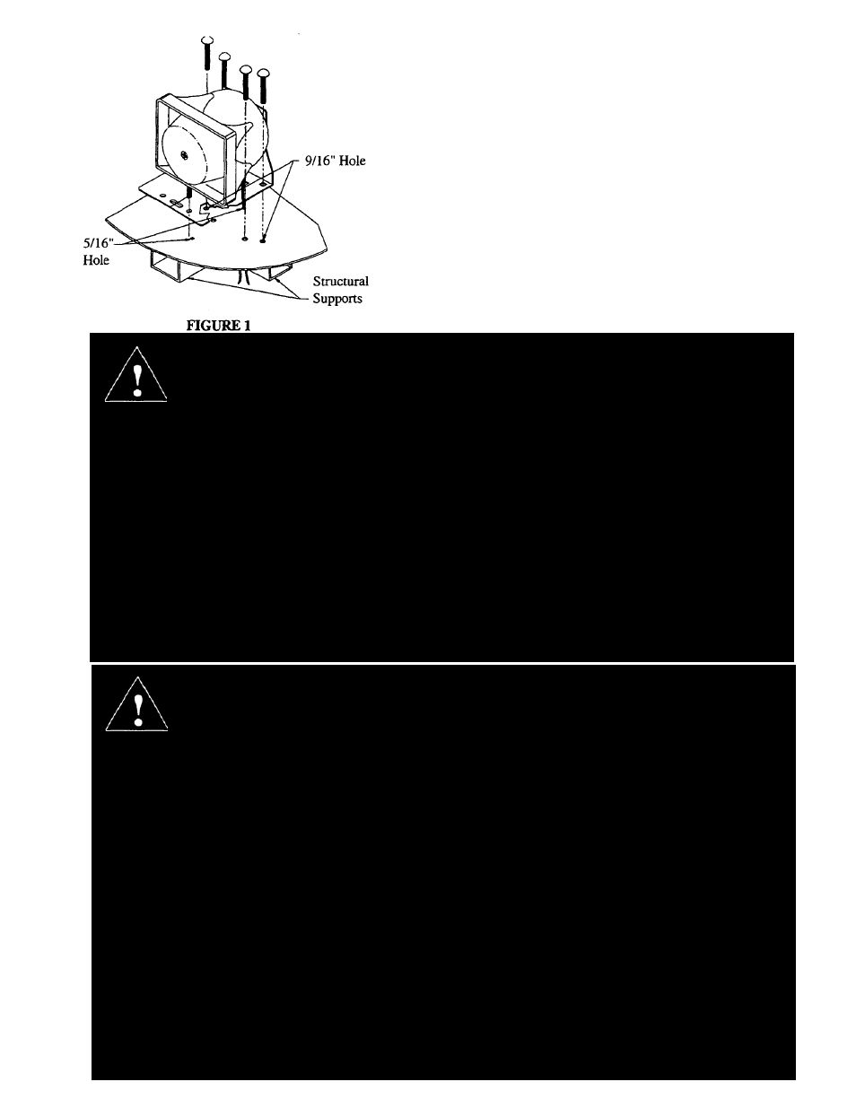
4) Connect the wires from the speaker assembly to
the leads coming from the siren control head. NOTE:
When this product is to be used in conjunction with
another speaker, both units must be connected in
phase.
To accomplish this, the white wire that is connected to
the number 1 terminal on the siren driver, must be
connected to the same output terminal on the
amplifier as the wire originating from the number 1
terminal on the second speaker. Likewise, the blue
wire that is connected to the number 2 terminal on
the driver, must be connected together with the wire
originating from the number 2 terminal on the second
speaker.
WARNING!
WARNING!
All devices should be mounted in accordance with the manufacturer’s instructions and
securely fastened to vehicle elements of sufficient strength to withstand the forces applied
to the device.
Ease of operation and convenience to the operator should be the prime consideration
when mounting the siren and controls. Adjust the mounting angle to allow maximum operator
visibility.
Do not mount the Contro
l
Head Module in a location that will obstruct the drivers view.
Mount the microphone clip in a convenient location to allow the operator easy access.
Devices should be mounted only in locations that conform to their SAE identification code
as described in SAE Standard J1849. For example, electronics designed for interior
mounting should not be placed underhood, etc.
Controls should be placed within convenient reach* of the driver or if intended for two
person operation the driver and/or passenger. In some vehicles, multiple con
t
rol
switches and/or using methods such as “horn ring transfer” which utilizes the vehicle horn
switch to toggle between siren tones may be necessary for convenient operation from
two positions.
* Convenient reach is defined as the ability of the operator of the siren systems to
manipulate the controls from his normal driving/riding position without excessive
movement away from the seat back or loss of eye contact with the road.
Larger wires and tight connections will provide longer service life for components. For high
current wires it is highly recommended that terminal blocks or soldered connections be used
with shrink tubing to protect the connections. Do not use insulation displacement
connectors (e.g. 3M® Scotchlock type connectors). Route wiring using grommets and
sealant when passing through compartment walls. Minimize the number of splices to
reduce voltage drop. High ambient temperatures (e.g. underhood) will significantly reduce
the current carrying capacity of wires, fuses, and circuit breakers. Use “SXL” type wire in
engine compartment. All wiring should conform to the minimum wire size and other
recommendat
i
ons of the manufacturer and be protected from moving parts and hot
surfaces. Looms, grommets, cable ties, and similar installation hardware should be used to
anchor and protect all wiring.
Fuses or circuit breakers should be located as close to the power takeoff points as possible
and properly sized to protect the wiring and devices.
Particular attention should be paid to the location and method of making electrical
connections and splices to protect these points from corrosion and loss of conductivity.
Ground terminations should only be made to substantial chassis components, preferably
directly to the vehicle battery.
The user should install a fuse sized to approximately 125% of the maximum Amp
capacity in the supply line to protect against short circuits. For example, a 30 Amp fuse
should carry a maximum of 24 Amps. DO NOT USE 1/4" DIAMETER GLASS FUSES
AS THEY ARE NOT SUITABLE FOR CONTINUOUS DUTY IN SIZES ABOVE 15
AMPS. Circuit breakers are very sens
i
tive to h
i
gh temperatures and will “false trip” when
mounted in hot environments or operated close to their capacity.