Maintenance, Electrical connections, Warning – Code 3 LED Triple Stack User Manual
Page 3
3
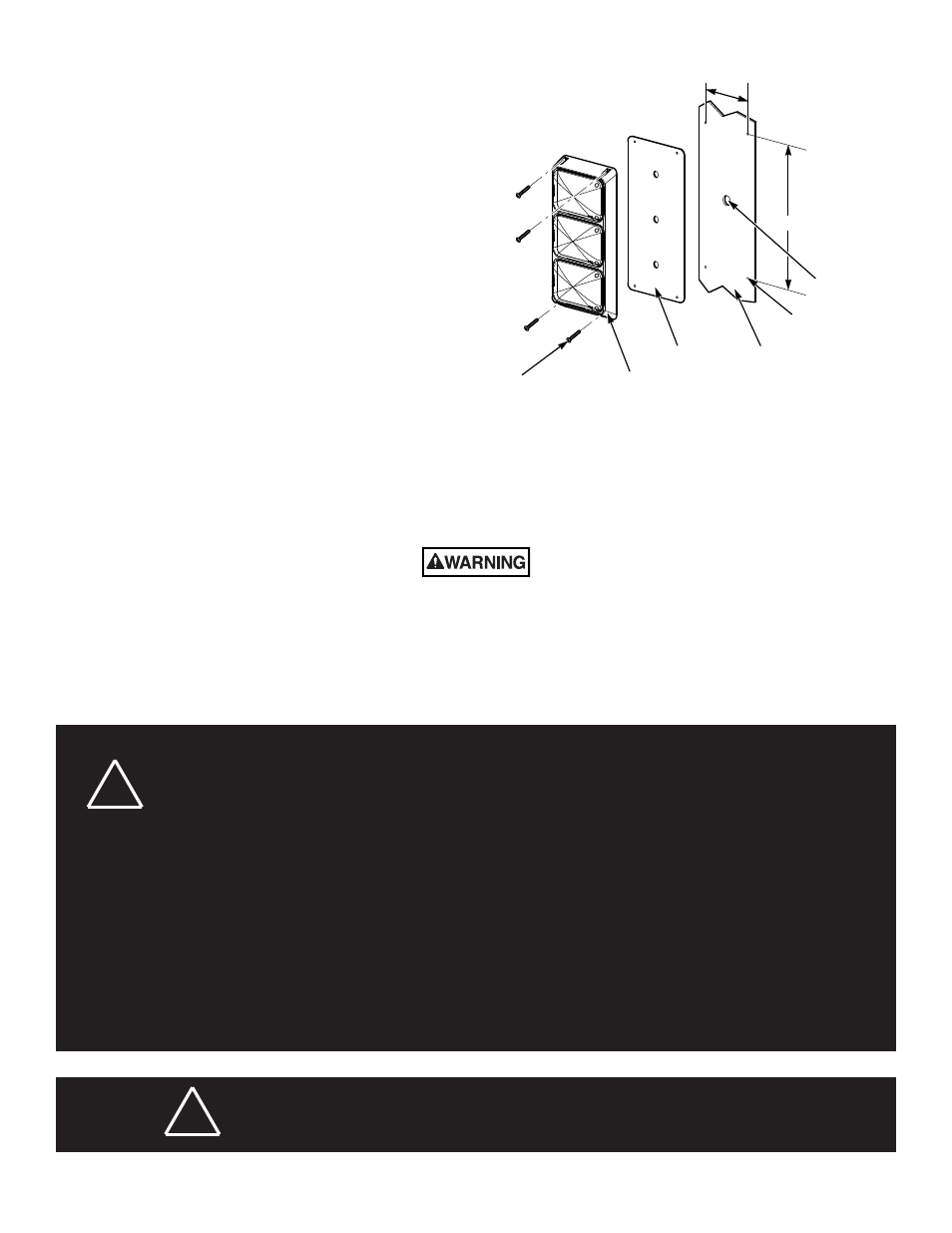
CABLE ROUTING
HOLE
5.75"
14.38"
Ø9/64" (4 PLACES)
#10 X 3/4"
SCREW(4)
QL64Z3V
MOUNTING
GASKET
VEHICLE
BODY
Using 18-gauge (minimum) wire, connect the red (+) lead to the positive
power source terminal for BRAKE mode, and the white (+) lead to a
different positive power source terminal for TAIL mode. The black (–) lead
should be connected to the negative power source terminal.
Two 12-inch-long lead wires are supplied for making electrical connections
to the turn arrow and reverse light assemblies.
Using 18-gauge (minimum) wire, connect the red (+) lead to the positive
power source terminal and the black (–) lead to the negative power source
terminal.
Figure 1.
MAINTENANCE
Crazing (cracking) of the lenses will cause reduced effectiveness of the light. Do not use cleaning agents (which will cause craz-
ing) such as strong detergents, solvents, or petroleum products. If crazing of the lenses does occur, the reliability of the light for
emergency signalling purposes may be reduced until the lenses are replaced.
To clean the plastic lenses, use a mild soap and a soft cloth. Remove fine scratches and haze with a non-abrasive, high quality, one-step, automotive
paste cleaner/wax and a soft cloth.
!
Larger wires and tight connections will provide longer service life for components. Do not use insulation displacement connectors
(e.g., 3M® Scotchlock type connectors). Route wiring using grommets and sealant when passing through compartment walls.
Minimize the number of splices to reduce voltage drop. High ambient temperatures (e.g., under-hood) will significantly reduce
the current carrying capacity of wires, fuses, and circuit breakers. Use “SXL” type wire in engine compartment. All wiring should
conform to the minimum wire size and other recommendations of the manufacturer and be protected from moving parts and hot
surfaces. Looms, grommets, cable ties, and similar installation hardware should be used to anchor and protect all wiring.
Particular attention should be paid to the location and method of making electrical connections and splices to protect these
points from corrosion and loss of conductivity. Ground terminations should only be made to substantial chassis components,
preferably directly to the vehicle battery.
The user should install a fuse sized to approximately 125 percent of the maximum amperage capacity in the supply line and
each switched circuit to protect against short circuits. For example, a 30-ampere fuse should carry a maximum of 24 amperes.
DO NOT USE 1/4” DIAMETER GLASS FUSES AS THEY ARE NOT SUITABLE FOR CONTINUOUS DUTY IN SIZES ABOVE
15 amperes. Circuit breakers are very sensitive to high temperatures and will “false trip” when mounted in hot environments or
operated close to their capacity. Fuses or circuit breakers should be located as close to the power takeoff points as possible
and properly sized to protect the wiring and devices.
WARNING
ELECTRICAL CONNECTIONS
The Triple Stack warning light assembly is designed to operate on 12 Vdc.
Three 12-inch long lead wires are supplied for making electrical
connections to the brake/tail light assembly.
WARNING
!
Any electronic device may create or be affected by electromagnetic interference. After installation of any electronic
device, operate all equipment simultaneously to insure that operation is free of interference.