Fig. 2, Fig. 3 – Code 3 920-07TH Flashers User Manual
Page 4
4
3. Locate the connectors shown in Fig 1. Disconnect these connectors
and connect the flashers connectors in line. Fig 2.
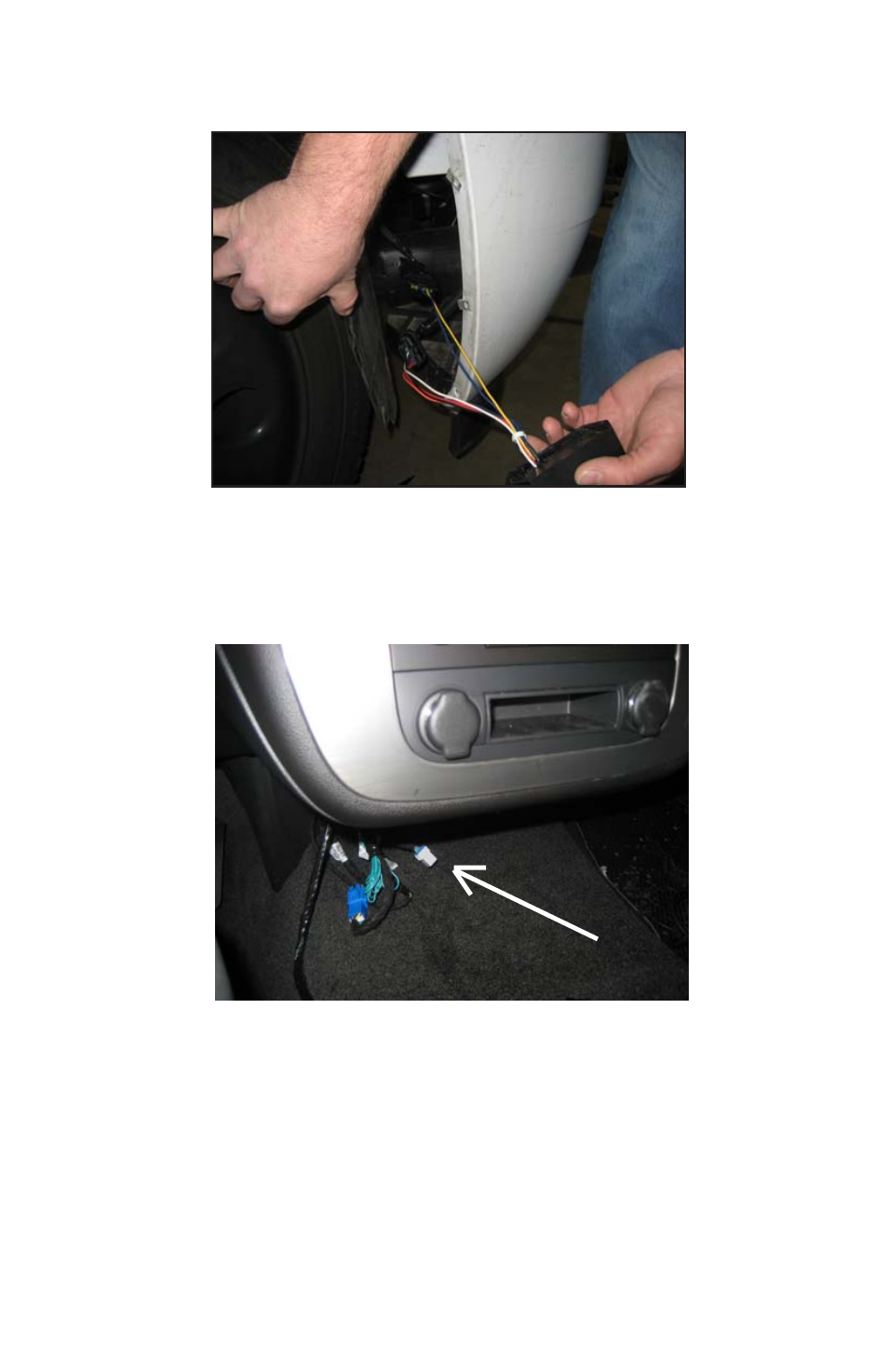
Fig. 2
4. Mount the flasher in this area using two screws (user supplied).
5. Locate the DARK GREEN/RED, 16-guage control wire under the center
dash section. Fig 3
6. Connect this DARK GREEN/RED wire to a customer supplied switch (12V
activation).
Fig. 3