Operation as a lightbar flasher, Mode 1 test, Mode 2 test – Code 3 710 and 711 Flashers User Manual
Page 5
Testing the Circuits for Headlight Flasher Modes 1 and 2.
Mode 1 Test
1)
Install the 20 amp. fuse in the in-line fuse holder.
2)
Turn ON the switch for Mode 1 operation. The high beam headlights should flash, the
pattern is dependent on flasher model.
Double check all of your connections then refer to the section on testing the circuit.
3)
Turn ON the vehicle’s low beam headlights. The low beams should burn steady.
NOTE: If you connected Terminal F, the headlight flasher will go off when you turn on the low beams. If
you want the high beams to continue to flash, DO NOT connect Terminal F.
4)
Turn ON the vehicle’s high beams. The high beams should now be on.
If the circuits do not work according to the above description, recheck all of your connections.
Mode 2 Test
1)
Install the 20 amp. fuse in the in-line fuse holder.
2)
Turn ON the switch for Mode 2 operation. The headlights should flash simultaneously.
If the circuits do not work according to the above description, recheck all of your connections.
Operation as a Lightbar Flasher.
To operate the Model 710 or 711 as a light bar flasher, perform the following steps:
1)
Jumper Terminal A to Terminal B and connect these to +12VDC in the light bar.
2)
Connect one bulb to be flashed to Terminal C and the other bulb to be flashed to Terminal D.
3)
Connect Terminal H to the frame of the light bar to provide ground (earth).
NOTE: The remaining Terminals may be used for special functions when switched to +12VDC.
•
Terminal E will “pause” or turn OFF the lamp until power is removed.
•
Terminal F will steady burn the bulbs for use as takedown or work lights until power
is removed. To operate as takedowns, power must be applied to +12VDC, A and B
input terminals.
•
Terminal G flashes the bulbs in a different flash pattern until power is removed.
Refer to the wiring diagram on the bottom of the unit for further assistance.
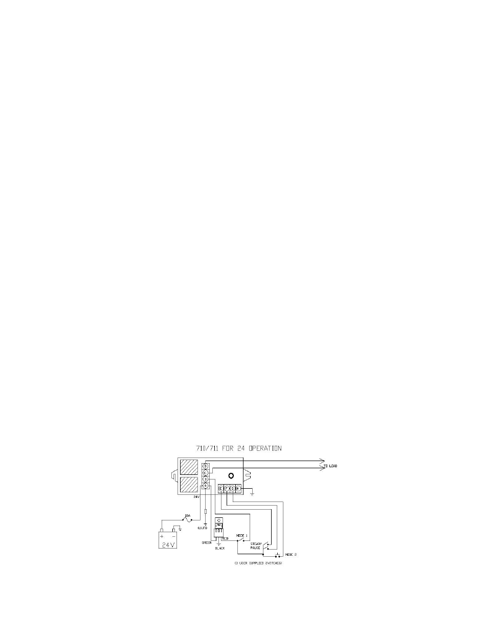
24V OPERATION