Warning, Wiring instructions – Code 3 275 Series Beacon User Manual
Page 5
5
WARNING!
!
Larger wires and tight connections will provide longer service life for components. For high
current wires it is highly recommended that terminal blocks or soldered connections be
used with shrink tubing to protect the connections. Do not use insulation displacement
connectors (e.g. 3M
®
Scotchlock type connectors). Route wiring using grommets and
sealant when passing through compartment walls. Minimize the number of splices to
reduce voltage drop. High ambient temperatures (e.g. under-hood) will significantly reduce
the current carrying capacity of wires, fuses, and circuit breakers. Use "SXL" type wire in
engine compartment. All wiring should conform to the minimum wire size and other
recommendations of the manufacturer and be protected from moving parts and hot
surfaces. Looms, grommets, cable ties, and similar installation hardware should be used to
anchor and protect all wiring.
Fuses or circuit breakers should be located as close to the power takeoff points as possible
and properly sized to protect the wiring and devices.
Particular attention should be paid to the location and method of making electrical
connections and splices to protect these points from corrosion and loss of conductivity.
Ground terminations should only be made to substantial chassis components, preferably
directly to the vehicle battery.
The user should install a fuse sized to approximately 125% of the maximum Amp capacity
in the supply line to protect against short circuits. For example, a 30 Amp fuse should
carry a maximum of 24 Amps. DO NOT USE 1/4" DIAMETER GLASS FUSES AS THEY
ARE NOT SUITABLE FOR CONTINUOUS DUTY IN SIZES ABOVE 15 AMPS. Circuit
breakers are very sensitive to high temperatures and will "false trip" when mounted in hot
environments or operated close to their capacity.
275 Magnetic Mount Beacon - The 275 Beacon can be equipped with a cord that plugs into a 12 Volt
D.C. cigarette lighter; rotate and push with reasonable moderate force which insures the best possible
connection.
Wiring Instructions
275 Permanent Mount Beacon - The 275 beacon is designed to operate on a 12 Volt D.C. negative
ground (earth) system. Use #18 GA. or larger wires. Connect black lead to vehicle chassis (earth),
or preferably the negative (earth) terminal of the battery. Bring the red lead to the user supplied
control switch, and then to the battery or to the stud on the battery side of the starter solenoid or
alternator. Install a fuse or circuit breaker of 8 Amp capacity in the supply line to protect the vehicle's
wiring system against short circuits.
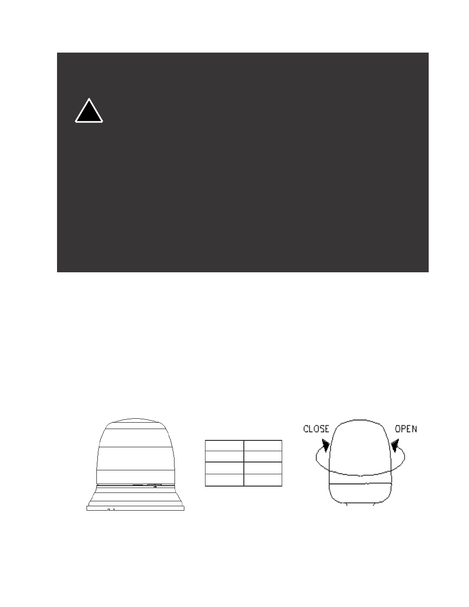
ANTI-THEFT SCREW
LENS OPENING AND CLOSING
LENS P/N
COLOR
T07982
RED
BLUE
T07983
T07984
AMBER