Appendix a: alarm i/o connector – AVer SF0311H-Z10 IP Cam User Manual
Page 60
56
Appendix A: Alarm I/O Connector
Some features of the Network Camera can be activated by the external sensor that senses physical changes
in the area Network Camera is monitoring. These changes can include intrusion detection or certain physical
change in the monitored area. For examples, the external sensor can be a door switch or an infrared motion
detector. These devices are customer provided, and are available from dealers who carry surveillance and
security products. Electrically, they must be able to provide a momentary contact closure.
This device provides a general I/O terminal block with one digital input and one output for device control.
The
pin 1 is located at the right side of terminal block from rear view.
Pin 2 and 3 can be connected to an external
sensor. The input vo
ltage will be monitored from the initial state ‘LOW’. If the external sensor need 12VDC
power, then it can connect to Pin1 (50mA maximum). The Alarm Output of pin 3 and 4 can be used to turn on
or off the external device.
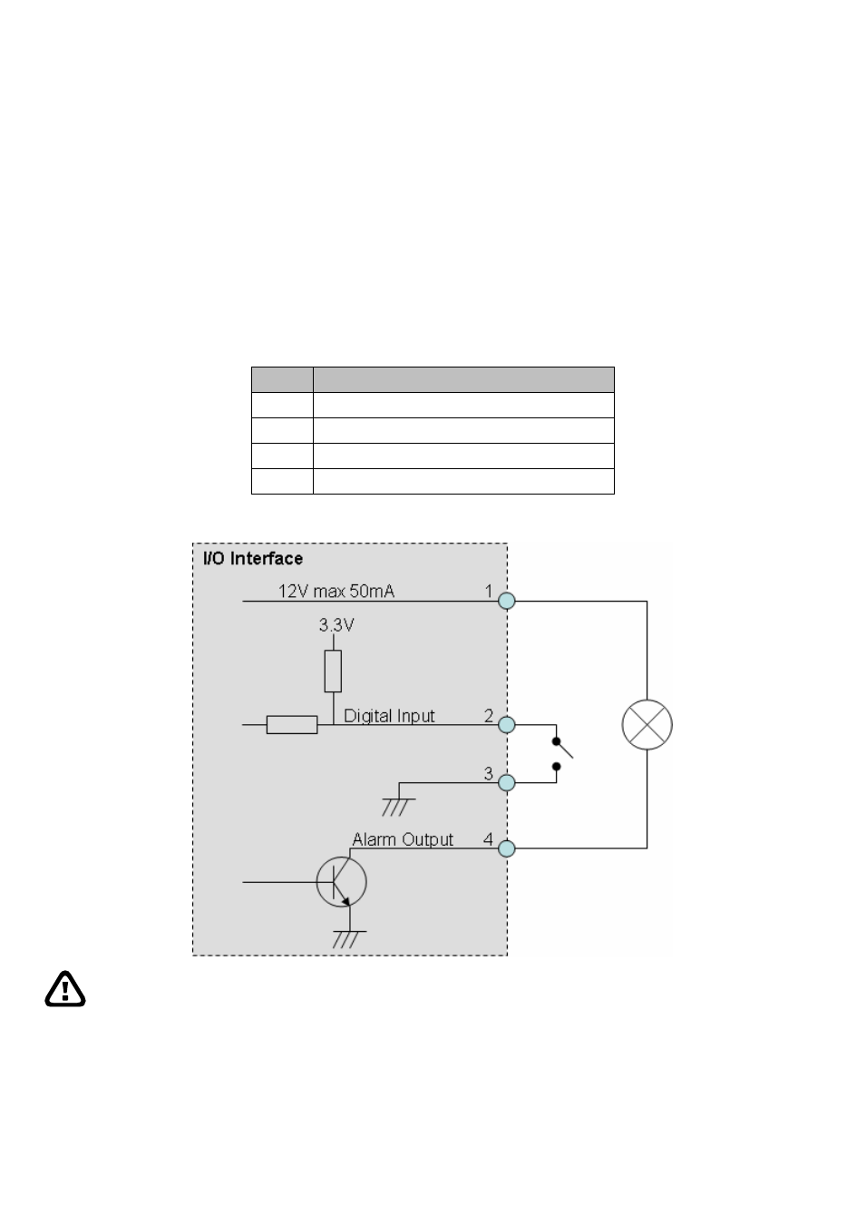
This Network Camera provides a general I/O terminal block as below:
Pin
Function
1
12VDC power supply (50mA maximum)
2
Alarm Input
3
GND
4
Alarm Output
Explanation of External I/O Circuit Diagram:
CAUTION
THE LOW VOLTAGE/CURRENT CIRCUITS AND HIGH VOLTAGE/ CURRENT CIRCUITS ARE IN THE
NETWORK CAMERA CIRCUIT. THE QUALIFIED ELECTRICIAN SHOULD DO THE WIRING NOT BY YOURSELF.
INCORRECT WIRING COULD DAMAGE NWTWORK CAMERA. YOU COULD RECEIVE THE FATAL ELECTRIC
SHOCK.
THE EXTERNAL I/O IS NOT CAPABLE OF CONNECTING DIRECTLY TO DEVICES THAT REQUIRE LARGE
AMOUNTS OF CURRENT. IN SOME CASES, A CUSTOM INTERFACE CIRCUIT (CUSTOMER PROVIDED) MAY
HAVE TO BE USED. SERIOUS DAMAGE TO NETWORK CAMERA MAY RESULT IF A DEVICE IS CONNECTED
TO THE EXTERNAL I/O THAT EXCEEDS ITS ELECTRICAL CAPABILITY.