4 operation – Crown Audio Power-Tech 1.1 User Manual
Page 10
Power-Tech .1 Series Power Amplifiers
page 10
Operation Manual
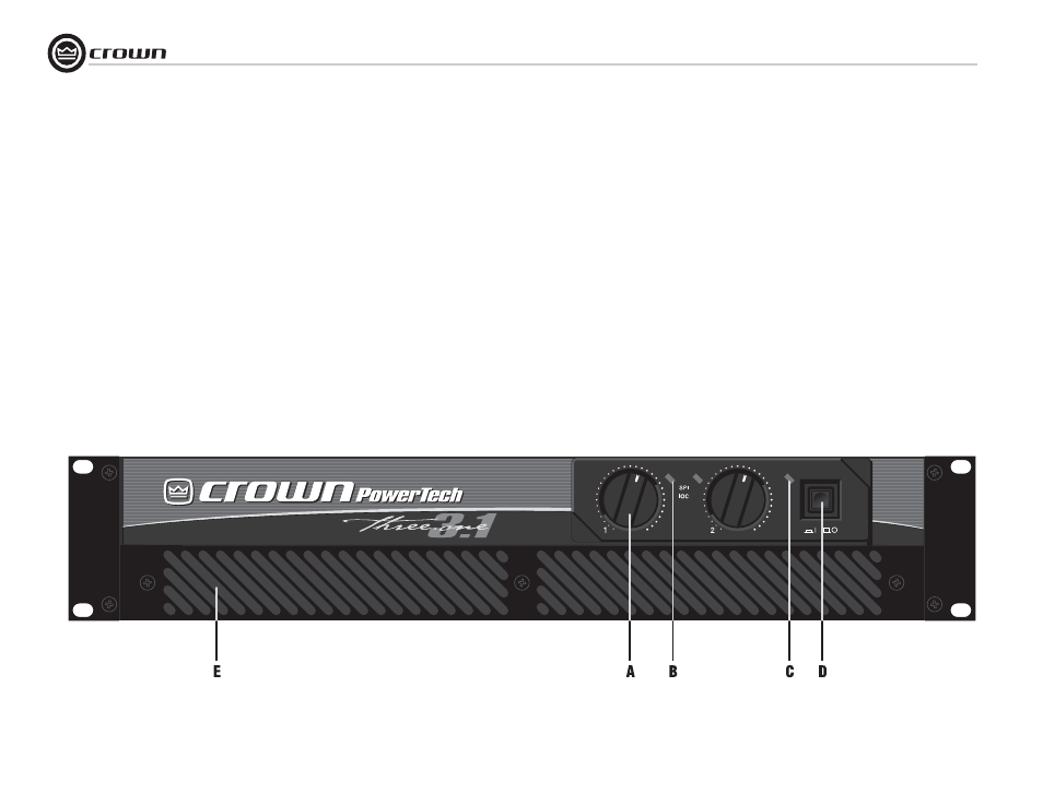
4.2 Front Panel Controls and Indicators
The diagram below explains the controls and indicators
on the front panel of the Power-Tech .1 Series.
A. Level Controls
Continuously variable level controls for each channel.
B. SPI/IOC Indicator
Dual-function indicator for each channel flashes green
for signal presence (SPI) and yellow if any distortion
exceeds 0.05% (IOC).
Figure 3.8 Power-Tech .1 Series Front Panel Controls and Indicators
C. Enable Indicator
Enable indicator shows the on/off status of the low-
voltage supply.
D. Power Switch
Power switch (and circuit breaker for the Power-Tech
1.1, Power-Tech 2.1 and 220/240 VAC Power-Tech
3.1).
E. Ventilation Grille
Removable grille and dust filter.
4 Operation