Installation step 9 – Craftsman 139.53674SRT User Manual
Page 20
Attention! The text in this document has been recognized automatically. To view the original document, you can use the "Original mode".
Installation Step 9
Electrical Requirements
To reduce the risk of electric shock, your garage
door opener has a grounding type plug with a third
grounding pin. This plug will
only fix
into a grounding
type outlet.
if the plug doesn't fit into the outlet you have,
contact a qualified electrician to install the proper
outlet.
To prevent electrocution or fire,
Installation
and wiring must be in compliance with local
electrical and building codes.
Do
NOT
use an extension cord, 2-wire adapter,
or change the plug in any way to make It fit
your outlet
To avoid Installation difficulties.
do not run the opener at titls time.
©
Right
Wrong
If permanent wirin
9
is required by your local code, refer to the following procedure:
To prevont electrocution^ remove
power from
the garage door opener
and
from the circuit
you plan to use for №e permanent connection.
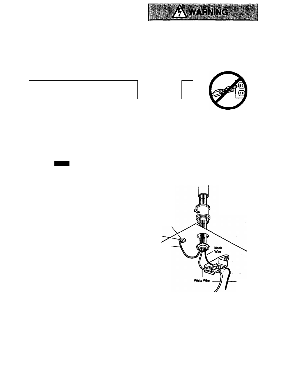
To make a permanent connection №rough the
7/8* diameter hole In the top of the opener
(according to local code):
• Remove the opener cover screws and set №e
cover aside.
• Remove the attached 3-prong cord.
• Connect the blad< (line) wire to the screw on the
brass terminal; the white (neutral) wire to the
screw on the silver terminal; and the ground wire
to the green ground screw.
The opener must be
grounded.
• Reinstall the cover.
Permanent
Wiring
Connections
GreundTab
Green
Ground
Screw
To avoid Installation difficulties,
do rtot run the opener at this time.
Ground
Wire
Black
Wire
20