Squaring the blade to the miter table, Adjustments – Craftsman 315.212220 User Manual
Page 17
Attention! The text in this document has been recognized automatically. To view the original document, you can use the "Original mode".
ADJUSTMENTS
The edge of the square and the saw blade should
be parallel as shown in figure 17.
If the front or back edge of the saw blade angles
away from the square as shown in figures 18 and
19, adjustments are needed.
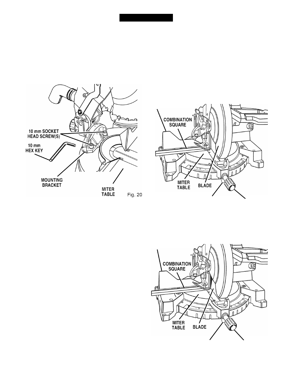
Using the 10 mm hex key provided, loosen the
socket head screws that secure the mounting
bracket to the miter table.
See Figure 20.
■
Rotate the mounting bracket left or right until the
saw blade is parallel with the square.
■
Retighten the screws securely and recheck the
blade-to-fence alignment.
SQUARING THE BLADE TO THE
MITER TABLE
See Figures 21-24.
■
Unplug your saw.
WARNING:
Failure to unplug your saw could
result in accidental starting causing possible
serious personal injury.
■
Pull the saw arm all the way down and engage
the lock pin to hold the saw arm in transport
position.
■
Loosen the miter lock handle approximately one-
half turn.
■
Depress the miter lock plate and rotate the miter
table until the pointer on the control arm is posi
tioned at 0°.
■
Release the miter lock plate and securely tighten
the miter lock handle.
Loosen bevel lock knob and set saw arm at 0°
bevel (blade set 90° to miter table). Tighten bevel
lock knob.
Place a combination square against the miter
table and the flat part of saw blade.
Note:
Make sure that the square contacts the flat
part of the saw blade, not the blade teeth.
Rotate the blade by hand and check the blade-to-
table alignment at several points.
The edge of the square and the saw blade should
be parallel as shown in figure 21.
FENCE
MITER
LOCK PLATE
VIEW OF BLADE
SQUARE WITH MITER TABLE
MITER
LOCK HANDLE
Fig. 21
If the top or bottom of the saw blade angles away
from the square as shown in figures 22 and 23,
adjustments are needed.
FENCE
MITER
LOCK PLATE
MITER
LOCK HANDLE
VIEW OF BLADE NOT SQUARE WITH MITER
TABLE, ADJUSTMENTS ARE REQUIRED Fig. 22
17