C. cabbubetob adjustments – Craftsman 358.797922 User Manual
Page 9
Attention! The text in this document has been recognized automatically. To view the original document, you can use the "Original mode".
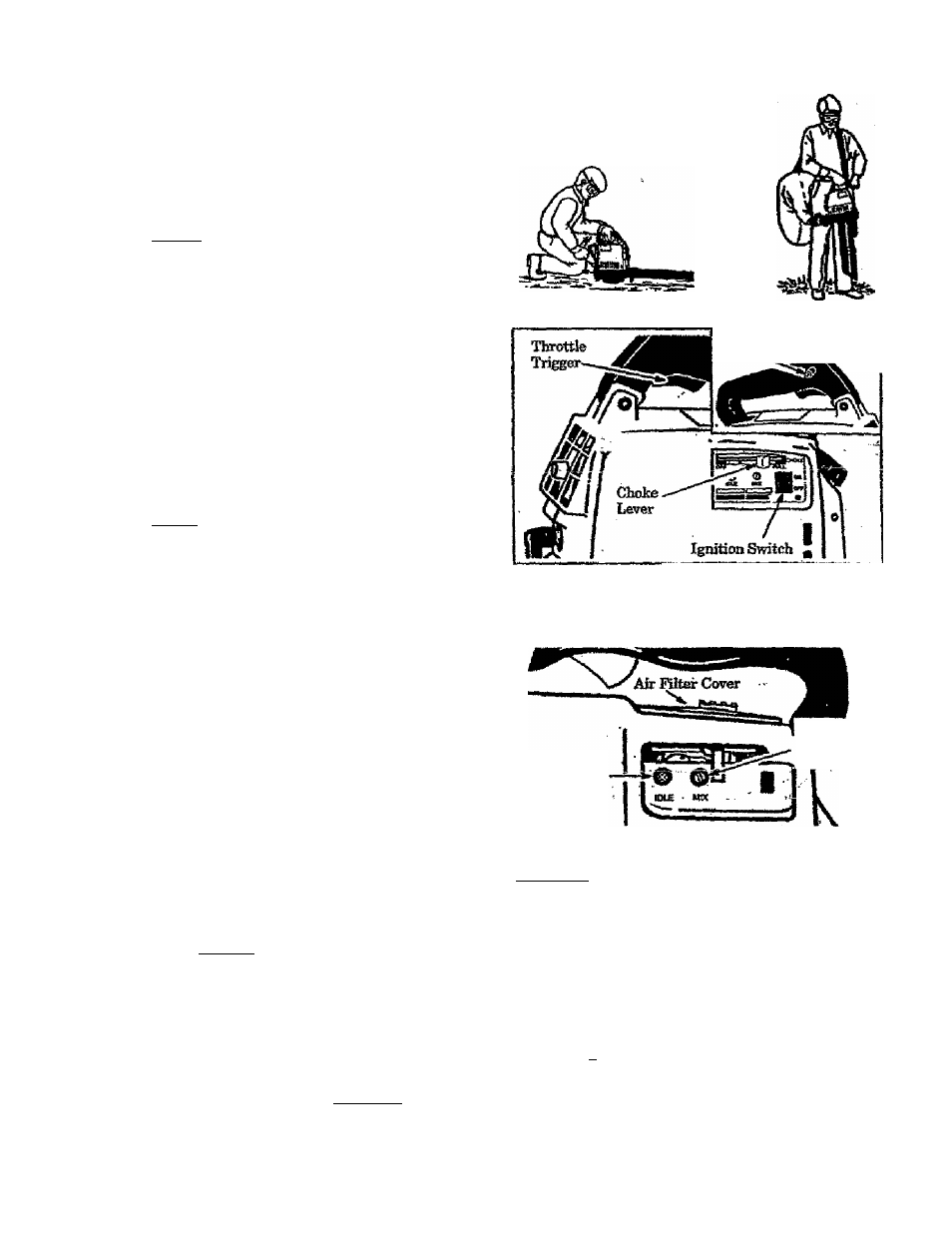
e. Move Choke to “HALF”. Figure 11.
£ Puil Starter Hope sham]^ until engtue runs,
but no more tkin 6 pul&.
HflSEtJf ^giue has not started after 5 pulls, re^
peat steps "a” throu^ “f.”
f.
Allow en^e to run &r 5 seconds, then move
Choke to “OFF" portion. Release Throttle
Lock hjr squeezing and releasing the Throttle
Trigger. Kgore 11.
KQTEh If engine dies with Choke at
"OFT"
posi*
tion, repeat steps "e” throng “g.” If engine does
not operate properly, refer to “Carburetor Adjust
ments.”
.
h. To stop engine, move ignition Switch to “OFF”
■ position. Figure 11.
3. For a Warm Engine;
a. Move the ignition Switch to the“ON” position.
Figure 11.
■
b. Move Choke Lever to the “HALF” position.
Figure 11.
c.
Engage Throttle Lock. Figure 11 Onset).
Diave throttle lock engaged thru step “d.”
d. Full Staler JStope sharply untfl engine runs,
but no nmie than Spills.
e. Move Choke to “OFF“. Figure 11.
f.
Release Throttle Lockby squeezing and releaS'
ing the Throttle Trigger. Figure 11.
HOTEi If engine does ncd; run after S pulls, it is
V. probably flooded. Wait a few minutra and repeat
! procedure with Chofe at "OFF” position.
g.
To stop engine, move Ignition Switch to
“OFF” positioa. Figure 11.
Blower
Stmrtittg
Position
Vacuum
Starting
PosititHa
(Model
m.7smi
ONLY)
Figure 10
Throttle Lock
Button.
Figure 11
C. CABBUBETOB ADJUSTMENTS
• Poor en^oJie performance can foe a residtdf
other causes snch as dirty air ffltejq caxhozt
• bnfld-up on muffler outlets, etc. See
■ . “Troafole Shooting Chart” heft>re proceed-
mg with carburetor adfustmeats.
• The carburetor has bem carehilly adjusted
at the f acto^ Due to changes in alti^e and op-
erettop condidpuf, yoiir c^faur^tor
require
low the.procedure below.
1, PjKEPARATION
au Use fresh fuel mix. See the “Fueling Your
Engine" section.
b.
Turn Mixture Screw (Figore 12) clockwise
until fuÜy closed, but do not overti^tea:
Figure 12. Turn mixture screw one fuß
tum cotmterdbckwise.
c.
Turn Idle Sp^d Screw (Figure 12) clock-
wisejiotilit stops. Do NOT overti^ten.
three fiiM turns countenJoek-
Wise.
IDLE SPEED ADJUSTMENT
a. Start the engine and run the unit for 10
minutes to warm up engine.
b. Allow the engine to return to idle speed.
~ar-Adjnst-Mls"^jBed Sergw^ntil tiie engine^
-15
Idi&S^â
Adjastment
Screw .
Mirtore
A^iustinmt
Screw
..Æ
Figure 12
1CAUTIQ^ The mixture setting Is a highly odti'
■ at Ml throttle for prolonged periods wMIe mai^g
the mixture adfusrnnent; The final nxfocture screw
setting sltoold be in^the^i^ge of 9/4,-tfèJl-1/4
open,
3, MKTDIIE ADJUSTMENTS
a. Accelsrate engine to fall throttle.
b.
Turn the Mixture Screw slowly clockwise
until ttie eng^e speed is reduced. Note posi
tion.
idles as
slowly
as possible
without
stalling..
- Tu^ screw efeckwis^^^igin^glalls.-. '.
— TiÄ 'Screw coühterâ^TOraë' to’slow eh* ■ *
gine down.
Turn the screw slowly counterclockwise. Stop
when tibe engine just be^ns to nm rtm^y.
Turn the screw slowly the minimiiSi
araoimt clockwise until the engine
smoothly.
. .
- 9 -