Assembly, B'blower tube assembly, A vacotjm bag assembly – Craftsman 358.797922 User Manual
Page 5: D. vacuum tube assembly awabning
Attention! The text in this document has been recognized automatically. To view the original document, you can use the "Original mode".
ASSEMBLY
A.PREFARATION
%nxr Operetoir^s Maxniid has been devejo{^ to h^
jpou assemble the uultand toimderstaitd its safe opera'
tkm.- It is iiai>ortai
2
t that you read your manual com
pletely to become familiar with the unit
hefore
you be-
t. BEAD YOliBOPERATOa'S MANUAL.
2» The
assembling tubes.
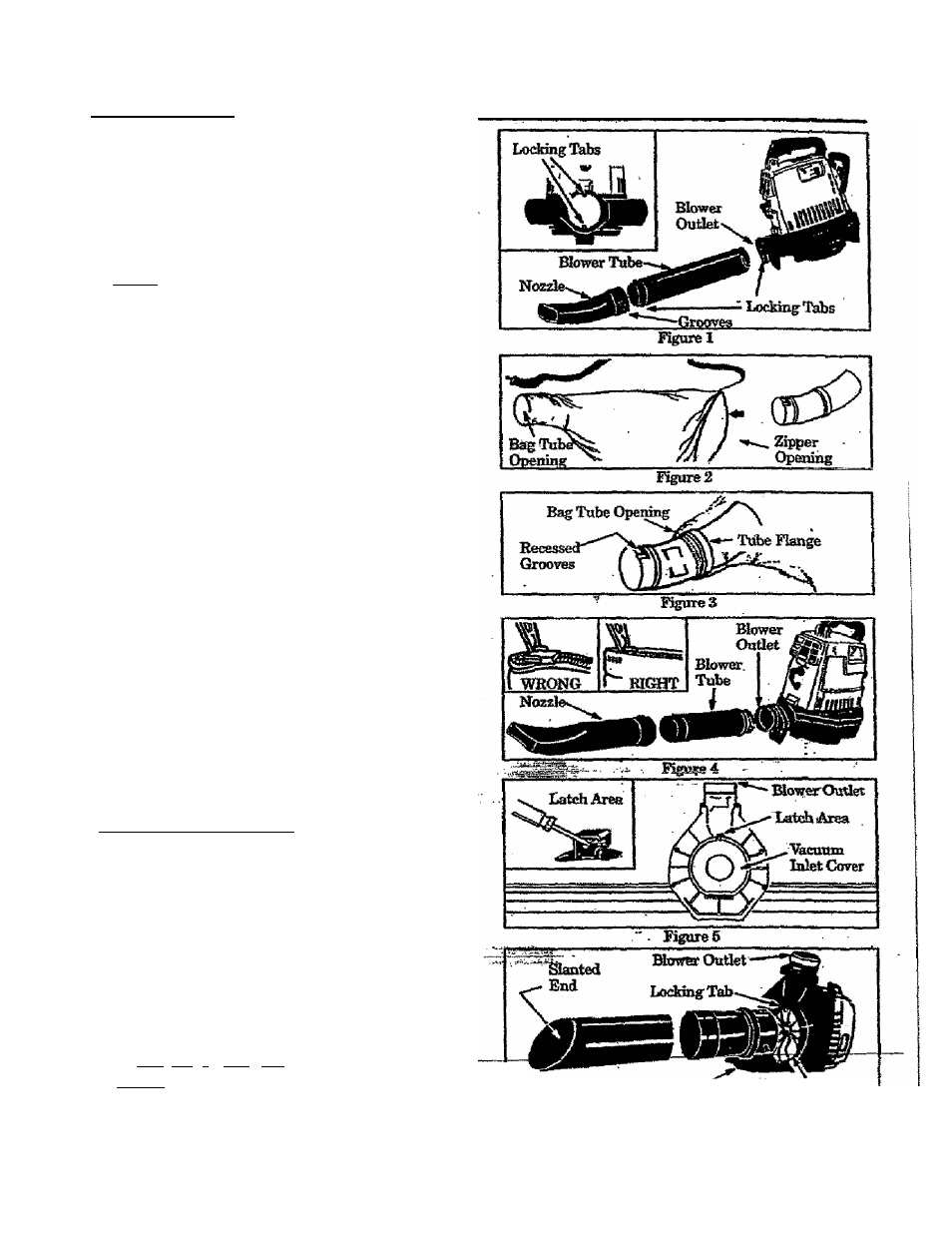
B'BLOWER TUBE ASSEMBLY
L
Locatethetwolockingtabsonthesideoftbeblower
tube. Figure 1.
2. AMgn the grooves on the hozrle with the locking
tabs on the blower tube and push the nozzle onto
the blower tube.
3. Tom the nozzle clockwise until the parts snap into
. place and are firmly ti^teued.
4.
Align Grooves on the Blower Tube with Locking
Tabsiathe Blower Outlet 0?gure 1, inset) andpu^
the Blower Tube into the Blower Outlet.
5. Tom the Blower Tidie clo«ikwise until the parts
snap into place and are firmly tighttaied-
a VACOtJM BAG ASSEMBLY
1. ' Opfio. the zijmer on thelai^ end of the vacurunhag.
2. Insert the Elbow Tube, grooved end first, throu^
_ the z%)p^ tpeningin the vaonim bag (Figure 2).
Then, pu^ the grooved end of the Elbow Tube
throughthebagtubecpemngin&eotfaerendofthe
bag. Kg^es2&3. Imke sure the bagtobeqpenmg
. is Qush against the tube flimge. Figure 3.
'3.-
caosetbezipt^onthebag.
fekesuretheKtoperis
'»dosed compLeteb^ and the zipper seam is tm£edto-
-ward the inside of the bag. Figure 4 Onset).
D. VACUUM TUBE ASSEMBLY
AWABNING
Stop the engine before opening the vactmm inlet
ntntobes.
Theeni^eniastbestoppecland&elni'
pdQ^. blades no longer torrilng to acvoid serions
injgry fifom the rotatingbladeg.
1. Remove the blower tube fimm the engine. Figure 4
2
.
Settheunit,bloweroutletup,onaflBtsuifaeeG^-
ure 3). Open the vacuum imet cover as follows:
a. Irwert a screwdriver into latA area. Figures,
h. -Gently twist the tip of tiie screwdriver and oj^
&e vacuum inlet <»ver with your other hand.
3i HoH open vacuum inlet^vCT ^d aliga ^e^tr^
side the vacumn inlet. Figure 6. Insert upper
vacutna into the vacuum miet; twist the upp®* vac
uum tube docfcwise imtil parts snap together.
4 Assemble the vacuum tubes by aligning the slanted
end of the lower vacuum tube witfi the Wowcroutlet
as shown in Figure 6,_Push the two tubes together
-until thcy are snug. Ftgui'g-fe
7
NOTE? The bottom end of the lower vacuum tube is
. ;?^,cut:at an angle. Mafes siire slanted end of vacuum
tuhe
h
aligned with blower ouilet. Figure 6.
Vacuum M?^.C
ovkc
; ; i', -'^tcuum.Ialet
----- .... ............................................ ------------