Hdv network module leds, Figure 11 – Cisco OL-12812-01 User Manual
Page 8
Connecting Cisco Voice Network Modules to the Network
IP Communications High-Density Digital Voice or Fax Network Module
8
Connecting Cisco Voice Network Modules to the Network
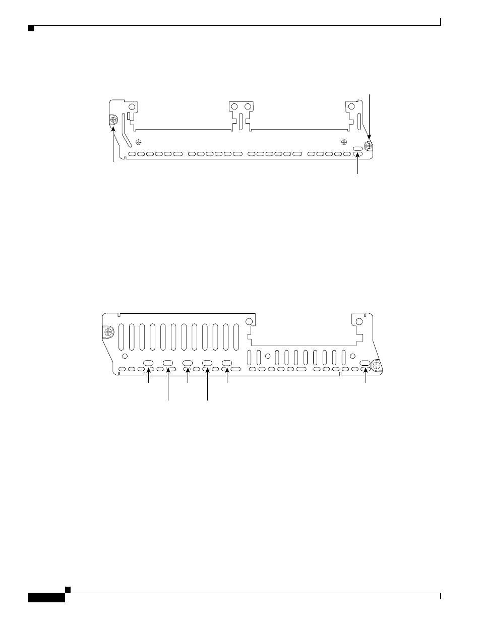
Figure 11
Voice Network Module LED
HDV Network Module LEDs
High-density network modules have an enable (EN) LED, and five LEDs for the PVDM banks,
numbered 0 through 4. The enable LED indicates that the module has passed its self-tests and is available
to the router. The BANK 0 through BANK 4 LEDs indicate the current operating condition of the
PVDMs installed on the card. (See
.) If the BANK LEDs do not come on after initial
installation and configuration, check that the PVDMs are properly seated in their slots.
Figure 12
HDV Network Module LEDs
IP Communications High-Density Digital Voice or Fax Network
Module
This section describes the IP communications high-density digital voice or fax (NM-HDV2) network
module. This module is available in three base-board stock-keeping units (SKUs):
•
NM-HDV2, with no built-in T1/E1 ports, shown in
•
NM-HDV2-1T1/E1, with one built-in T1/E1 port, shown in
•
NM-HDV2-2T1/E1, with two built-in T1/E1 ports, shown in
VOICE
2V
V0
V1
EN
Enable
LED
H10833
Module
screw
Module
screw
NM-HDV
BANK 4 BANK 3 BANK 2
V0
EH
BANK 1
22161
BANK 0
BANK 4
LED
BANK 3
LED
BANK 2
LED
BANK 1
LED
BANK 0
LED
ENABLE
LED