Installation instructions, Warning, Caution – Sony SAT-A3 User Manual
Page 107
Attention! The text in this document has been recognized automatically. To view the original document, you can use the "Original mode".
> Warning
• Do not install the antenna near power lines.
> Caution
• Do not install the antenna where it could be humped or jarred by
people, furniture, doors or pets.
•
Do not attempt any installation in rainy or windy conditions.
Installation instructions;
1
Choose a flat and secure location to install the antenna.
2
Tap the cinder blocks with a hammer to find the hollow center
Remove the mast and drill a
'/2"
hole.
Note
• Fill mixlakes with mortar or silicone sealant.
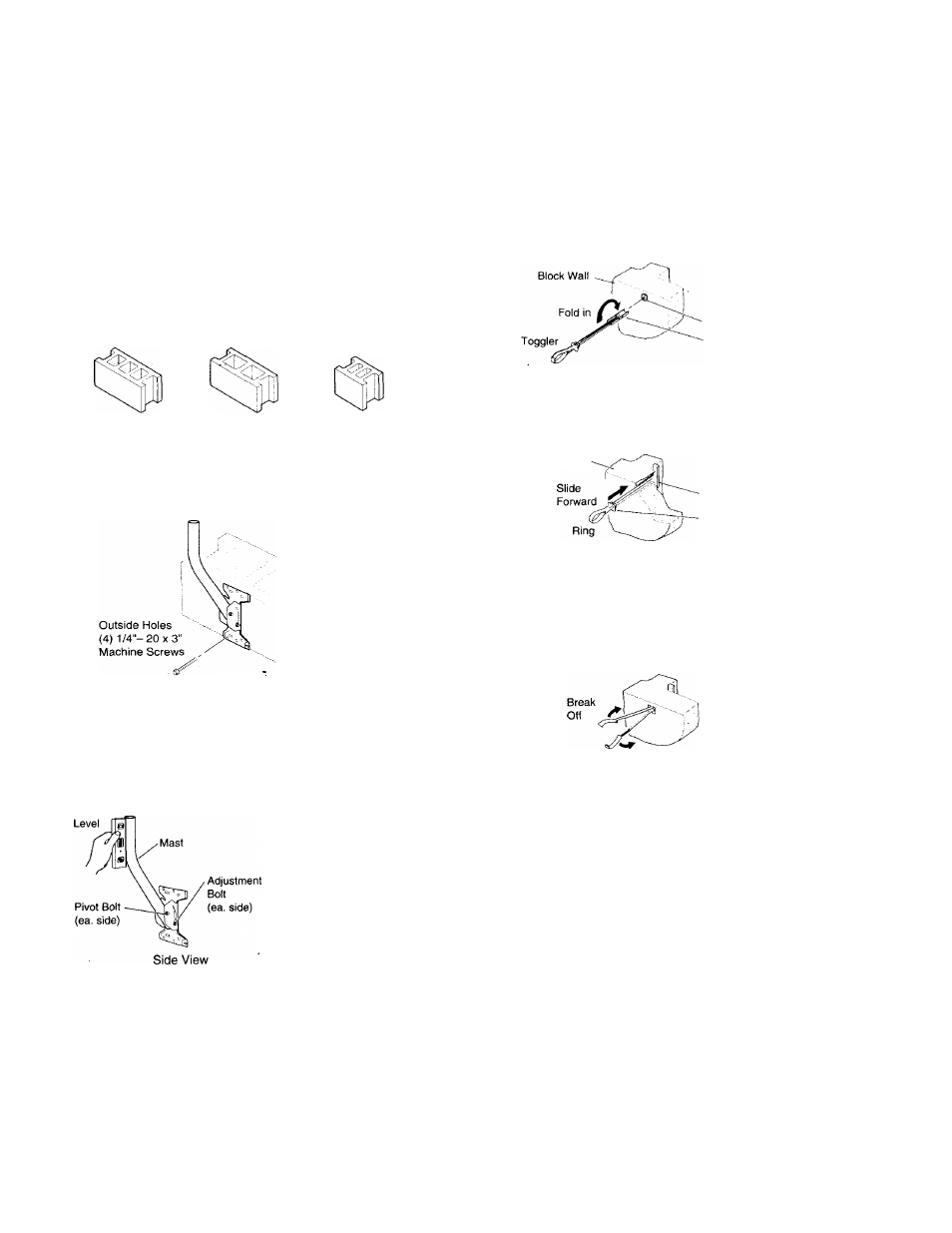
7
Install a toggler.
A)
Fold the metal channel flat against the toggler and insert
it into the hole until the channel opens.
Metal Channel
16" Three Core
16" Two Core
8" Two Core
B)
Pull the toggler toward you to apply tension while sliding
the plastic cap until it is snug against the wall.
3
Position the four outer holes of the base plate over the hollow
center cores of the cinder block and hold the base plate in
position.
Block Wall
4
Use a level to determine whether the mast can be -vertically
aligned before you drill any holes.
Note
•
The mast must be vertically level to aim the antenna properly.
90'
Mast
'Level the Pole
at Right Angles
Metal Channel
Plastic Cap
Note
•
The toggler must lie completely flat against the inside of the cinder
block to be effective.
C)
Break the ring along the center perforation and push the
two halves away from each other. Push them toward the
wall until they break at the plastic cap.
Top View
8
Use a machine screw
('/4"
- 20 x 3") to attach the mast to the
cinder block. Do not tighten the screw too securely to allow
for adjustment.
9
Check to make sure the mast is still level.
10
Mark the remaining three outer holes., and repeat steps 6
through 9.
11
Tighten all four bolts.
Proceed to
Installing the Antenna
on page 14.
A) -Loosen the pivot bolts and adjustrnent bolts that connect
the bottom of the mast to the base plate and align the
mast in a vertical position.
B)
Place the level along the top part of the mast and take
two readings 90° apart from each other.
C)
Tighten the pivot bolts and adjustment bolts.
5
Mark the upper left hole of the base plate with the pencil.
13