Location and function of controls, O picture control – Sony CPD-9000 User Manual
Page 3
Attention! The text in this document has been recognized automatically. To view the original document, you can use the "Original mode".
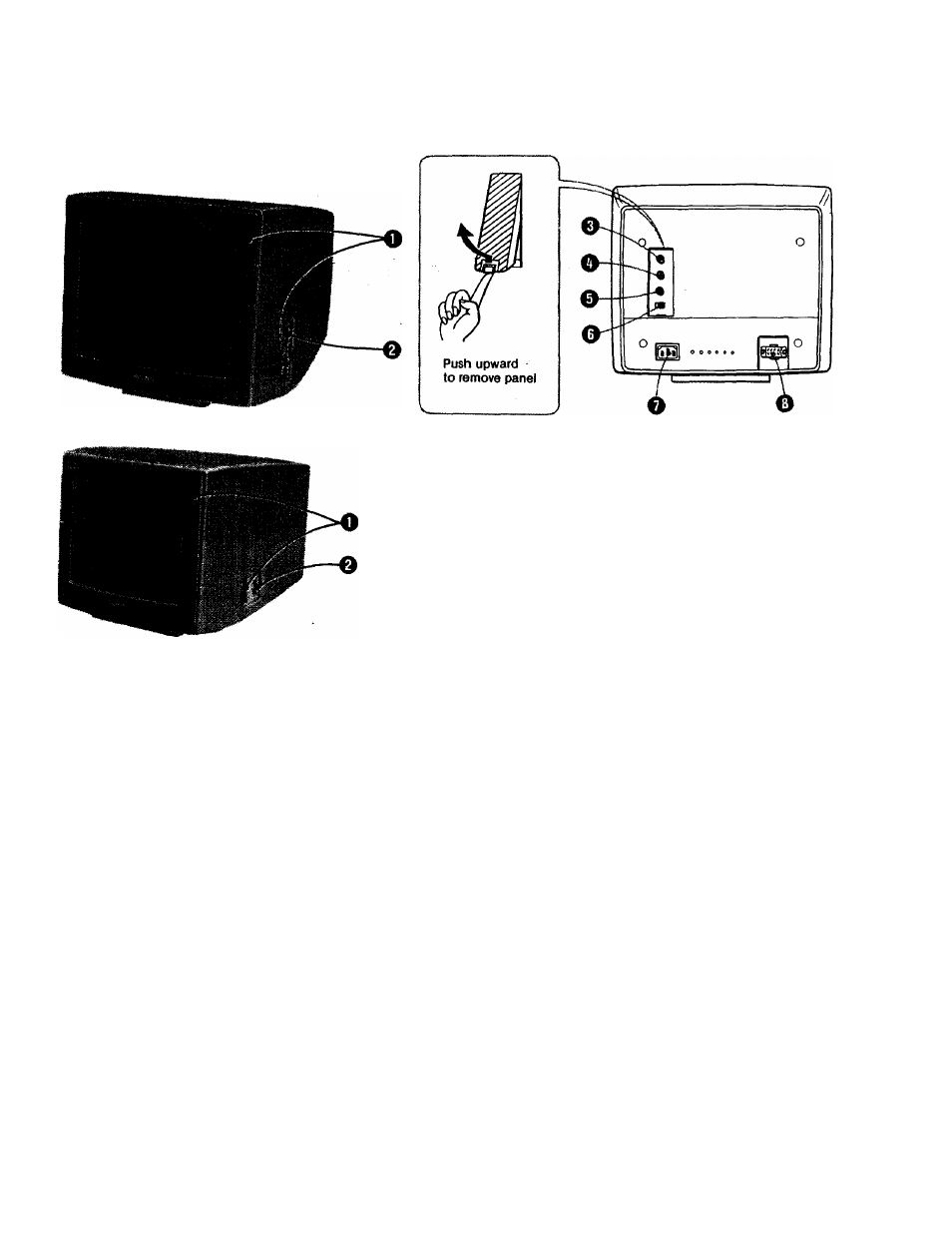
LOCATION AND FUNCTION OF CONTROLS
CPD-1201
CPD-9000
O POWER switch and indicator (green)
To turn on thè power of the unit, press this switch to ON.
The indicator will light up. To turn off the unit, press
towards OFF.
ON
OFF
O PICTURE control
Adjusts the contrast. Turn downwards to increase con
trast, or upwards for less contrast.
O ROB input selector
Depending on the RGB output of the equipment you
have connected, set this switch to one of the following 3
positions.
ANALOG; For microcomputers and videotex units
having analog RGB output, such as the Sony
SMC-70, SMC-70G microcomputer.
DIGITAL 1: For microcomputers having digital RGB
output with positive sync signals, such as the IBM
PC, IBM PC XT and IBM PCjr.
DIGITAL 2: For microcomputers having digital RGB
output with negative sync signals, such as the NEC
PC-8001 A.
O AC power input connector
Connect to the AC outlet with the supplied AC power
cord.
O RGB IN (input) connector (8-pin)
Allows a microcomputer, a character generator or a
videotex unit having either analog or digital output to be
connected.
Refer to pages 4-5.
O BRIGHTNESS control
Normally keep this control at the center detent position.
For a brighter display, turn this knob clockwise and for a
darker display, turn it counter clockwise.
O H SHIFT (horizontal shift) control
Turn this control to center the displays of microcom
puters, character generators, etc. not of Sony that are
shifted toward the left or right side of the screen.
0 V HOLD (vertical hold) control
If the display rolls vertically, adjust this control until the
display stabilizes.