Taylor-Wharton KeepFull Telemetry System User Manual
Page 6
Installation
Before installing the telemetry unit inspect it carefully.
Report any damage to the carrier and Taylor Wharton
Customer Service. As shipped, the unit is operational and
ready to be installed on the tank. For installation on a
typical tank with an existing Contents Gauge follow these
steps.
1) Fill out the Bulk Vessel Registration Form supplied with
this manual and fax it to Taylor Wharton Customer
Service. This form, along with the Customer Informa-
tion Form, filled out at the time of purchase is used to
prepare your Internet Web Site.
2) Verify that the differential pressure transmitter span
(inches of water) covers the range required for the
tank.
3) Record the present liquid level and tank pressure as
indicated on the existing Contents Gauge Assembly.
Also, label the high and low-pressure instrument lines.
4) Close both instrument valves to isolate the existing
Contents Gauge Assembly from the tank. Open the
Instrument Bypass valve to equalize the pressure
between the high-pressure and low-pressure side of
the Contents Gauge Assembly.
5) Carefully loosen the connections at the Contents
Gauge Assembly to relieve any pressure and then
remove the assembly.
6) Identify the high (H) and low-pressure (L) sides of the
Differential Pressure Transmitter on the Telemetry Unit.
7) Mount the Telemetry Unit on the tank using the sup-
plied bolts. See figure 2. The Telemetry Unit bracket
is designed to mate to a typical bracket supplied with
the tank. If there is a mismatch some field adaptation
may be required.
8) Solar panel must be directed to maximize southern sun
exposure. Turn the solar panel by rotating the 45°
elbow as much as one-quarter turn to direct the panel
to a maximized southern sun exposure. Caution, only
apply torque to 45° elbow using appropriate
wrenches.
9) Install an appropriate pressure gauge in the tee at the
low-pressure side of the telemetry unit. See figure 2.
10) Connect the instrument lines and then open the
instrument valves.
11) Leak test all connections using a suitable liquid leak
detector.
12) To obtain the current reading momentarily hold the “Fill
Button” until you see “FILL” on the display. The screen
will blink with the current reading. If “ERROR” is
displayed the high and low-pressure connections are
most likely reversed.
13) Activate your website.
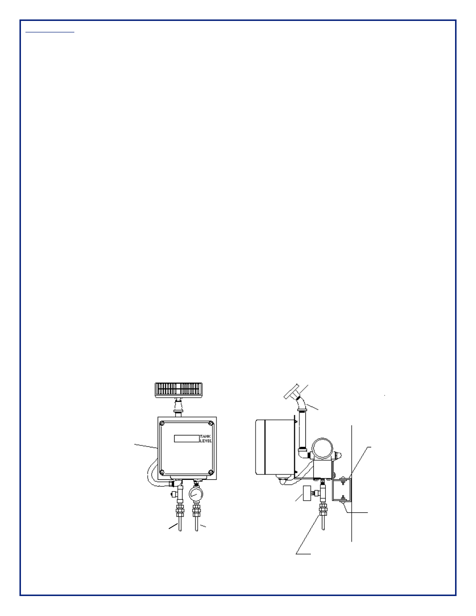
Figure 2: Typical Installation
Notes:
All supplied pressure parts are
suitable and have been cleaned for
oxygen service. All field installed
parts must have a pressure rating
equal to or higher than the tank
MAWP, be suitable for oxygen service
and likewise cleaned. See the safety
precautions in the front of this
manual.
Seal all pipe threads using Teflon tape.
Figure 2: Typical Installation
Solar Panel
45-degree Elbow
Existing Tank Bracket
Screw and Locknut
Supplied With Unit
4 Places
Tube Adapter From
Instrument Tube Size
Connecting to 0.25” FNPT
Tank
Pressure
Gauge
Low
Pressure
Tap
High
Pressure
Tap
Telemetry
Unit
6