T&D Machine Products Brodix Big Block Chevy User Manual
Page 2
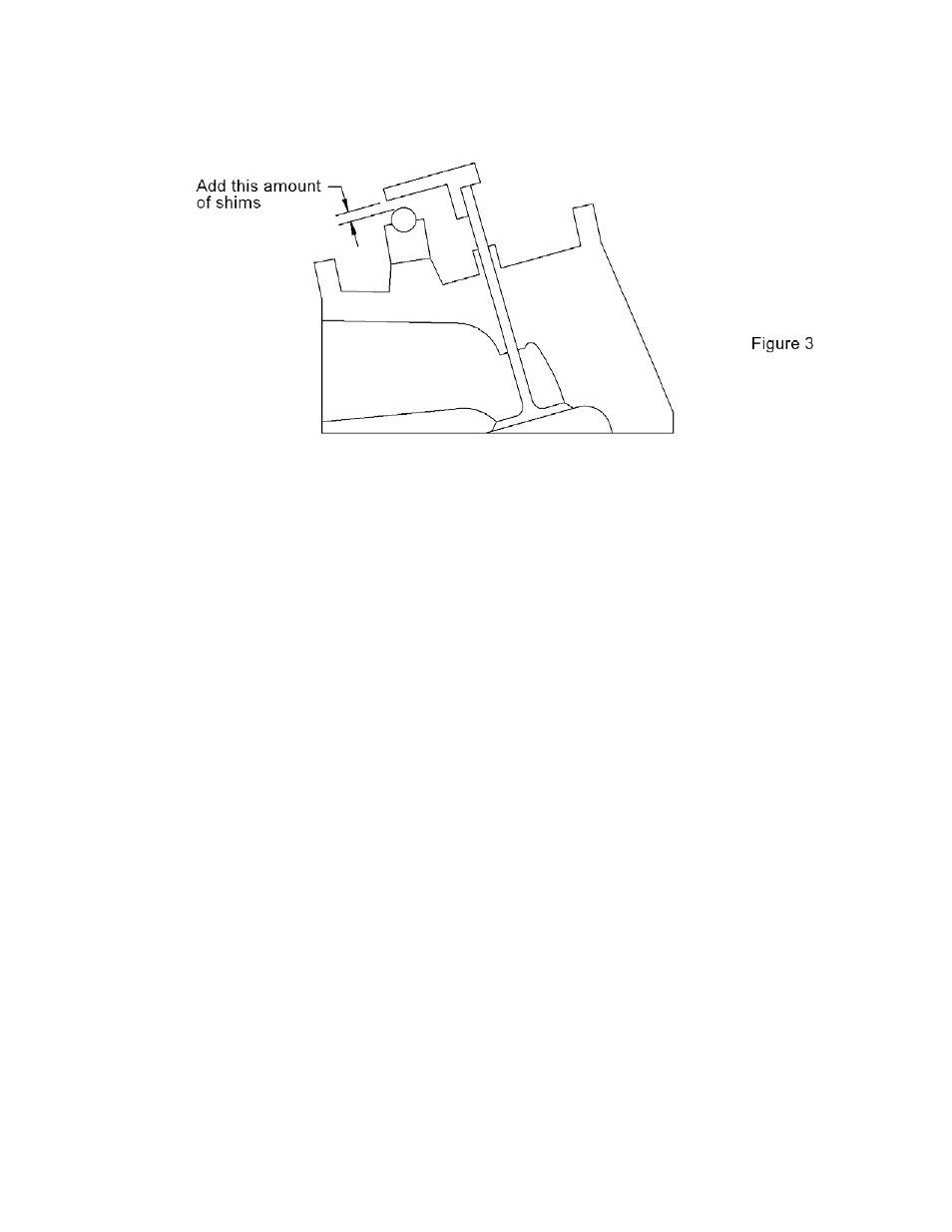
If the gage contacts the top of the valve stem and does not touch the rocker shaft,
as shown in Figure 3, add a corresponding amount of shims between the stand and the
cylinder head. This will raise the rocker stand and shaft to the correct height.
NOTE:
The shaft height gage supplied with this assembly is manufactured for 0.750" of valve lift.
For lifts less than 0.750", the shaft height should be raised by half the difference, and for
lifts greater than 0.750" lift, the shaft height should be lowered by half the difference.
(i.e.: For 0.800" lift, the shaft should be 0.025" lower than the gage, and for 0.650"
lift, the shaft should be 0.050" higher than the gage.)
2.
INSTALL ROLL PINS
After making any necessary height adjustments, install each stand in their respective
positions. Align the stand with the valve and tighten the stand attaching bolts to keep
them from rotating. Use the stand as a guide, or use a transfer punch to drill the 1/4"
holes for each roll pin, 1/2" deep. When all the roll pin holes are drilled, install the
included roll pins by lightly tapping with a hammer.
3. DETERMINE
CORRECT PUSHROD LENGTH
Place a pushrod length checker into the lifter and install the rocker arm assemblies.
Be sure the cam is rotated to the base circle. Seat the bottom of the adjuster screw up
against the recess in the rocker arm and turn the adjuster screw clockwise one full turn
down. This is the initial adjuster position. Adjust the pushrod length tool to the proper
length, remove from the engine, and measure its overall length.
The rocker arm should not be operated with the adjuster screw more than one turn
up or down, from the initial adjuster position. Doing so can cut off the flow of oil to
the
rocker
arm.