T&D Machine Products Chrysler B-1 Rocker Arm Assembly with 5/8" diameter rocker shafts User Manual
T&D Machine Products Accessories for water
INSTALLATION INSTRUCTIONS
Please follow these instructions to ensure the proper operation of your T & D MACHINE
PRODUCTS Chrysler B-1 Rocker Arm Assembly with 5/8" diameter rocker shafts.
1.
CYLINDER HEAD INSPECTION AND PREPARATION
Inspect the cylinder heads to be sure they are clean and free of any burrs that may
interfere with the rocker stands. Inspect the tapped holes for proper thread depth.
Minimum thread depth is 3/4". This rocker system is designed to oil through the
pushrods, so the block and lifters must be modified accordingly. Also, the oil
supply holes in the cylinder head must be plugged to prevent leaking by tapping the
oil holes for a 12-24 set screw.
2.
DETERMINE CORRECT STAND HEIGHT
Install the rocker stands on the cylinder head using the 3/8-16, 12 point attaching
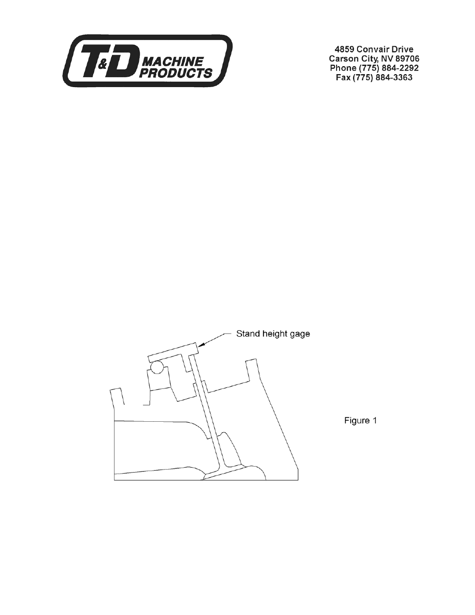
bolts. Remove a rocker arm from one of the shafts and place that shaft on a
stand. Take the shaft height gage supplied with the kit and place it on the valve
stem as shown in Figure 1.
The gage should contact the top of the valve and the rocker shaft as shown in
Figure 1.
If the gage contacts the shaft before touching the top of the valve stem, as shown
in Figure 2, remove a corresponding amount of material from the stud bosses on
the cylinder head. This will lower the rocker stand on the cylinder head.