Installing in existing homes, Figure 6, Figure 7 – Qmark MM698 Combination Fans User Manual
Page 3
INSTALLING IN EXISTING HOMES
1.
Review the section: “New Home Installation” and follow instructions where applicable.
2.
Refer to wiring diagram for wiring and for duct work.
3.
Drill a small hole in proposed location, then locate this hole in the attic.
4.
In the attic, position housing between ceiling joists and over drilled hole. Using the housing as a template, mark ceiling
for cutout. Make cutout on this line.
5.
Remainder of the installation is the same as Steps 4 through 9 under “New home Installation.” Cracks between
housing and ceiling may be plastered or caulked.
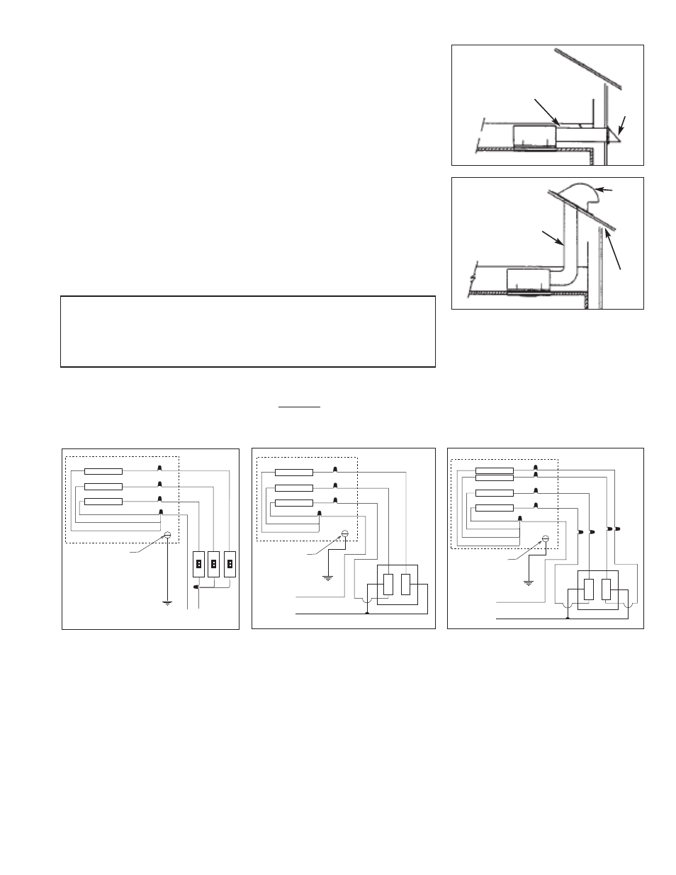
FIGURE 6
4" ROUND DUCT
WALL
CAP
FIGURE 7
ROOF
CAP
ROOF
4" ROUND DUCT
OUTLET BOX
LIGHT
VENTILATOR
HEATER
BLACK
BLACK
WHITE
W
H
IT
E
B
L
A
C
K
B
L
A
C
K
G
R
O
U
N
D
WHITE
WHITE
WHITE
MARLEY
COMBO
SWITCH
RECEPTACLE
GROUND
SCREW
120 VAC
60HZ
SUPPLY
RECEPTACLE
RECEPTACLE
OUTLET BOX
LIGHT
VENTILATOR
HEATER
WHITE
W
H
IT
E
B
L
A
C
K
B
L
A
C
K
B
L
A
C
K
B
L
A
C
K
BLACK
BLACK
BLACK
G
R
O
U
N
D
WHITE
WHITE
RECEPTACLE
GROUND
SCREW
120V AC
60 HZ
SUPPLY
WALL
SWITCH
SWITCH
SWITCH
WALL
WALL
RECEPTACLE
RECEPTACLE
7. Attach four inch diameter duct to duct adapter and run to roof cap or
wall cap. See Figs. 6 & 7.
8. Run 120V AC, 60Hz power cables from wall switches to appropriate
knockout in housing and attach using a BX or Romex connector.
NOTE: Each mode of the unit heat/light/fan will require an individual
cable from the switch/control. Refer to the wiring diagram designated
for the model being installed.
9. Connect cables to receptacle wires in the unit using approved wire
connectors. Connect ground wire to ground (green) screw in unit.
10. Restore ventilating section to its original location. Be sure to engage
plate with tabs and fasten it with retaining screw “B”. Push plug “R” into
receptacle.
11. Restore heating unit to its original location. Tighten retaining screws
“A”. Push plug “P” into receptacle.
12. Remove lens from grille assembly by squeezing both sides. Lift grille
assembly to unit and push plug into light receptacle “S”. Engage the
long mounting screw into formed hole in cover plate. See fig. 1. Tighten
until grille is snug against ceiling.
13. Install 100 watt maximum type A-19 bulb and on model MM728NL a
7-1/2 watt candelabra base C-7 night light bulb. For model MM698F,
install a 13 watt twin or quad tube 2-pin compact fluorescent lamp.
Snap the lens into it’s original location.
Models:
MM698,
MM698F
Model:
MM698WC
LIGHT
HEATER
VENTILATOR
BLACK
WHITE
W
H
IT
E
B
L
U
E
R
E
D
G
R
O
U
N
D
WHITE
WHITE
WHITE
MARLEY
COMBO
SWITCH
RECEPTACLE
GROUND
SCREW
120 VAC
60HZ
SUPPLY
RECEPTACLE
RECEPTACLE
B
R
O
W
N
Y
E
L
L
O
W
BLACK
BLACK
BROWN
RECEPTACLE
NIGHT LIGHT
WHITE
BLUE
OUTLET BOX
Model:
MM728NL
CAUTION - Grille Assembly is intended for installation in one direc-
tion only. Plug “S” & lamp socket must be installed on same side of
fan as Light/Night Light outlet shown in Figure 1. Improper orientation
of the Grille Assembly will result in overheating of the grille and a
possible safety hazard.