Fig. 3 fig. 4, Trouble shooting chart, Symptom possible causes corrective action – Qmark GV16 - Attic Ventilators User Manual
Page 3
3
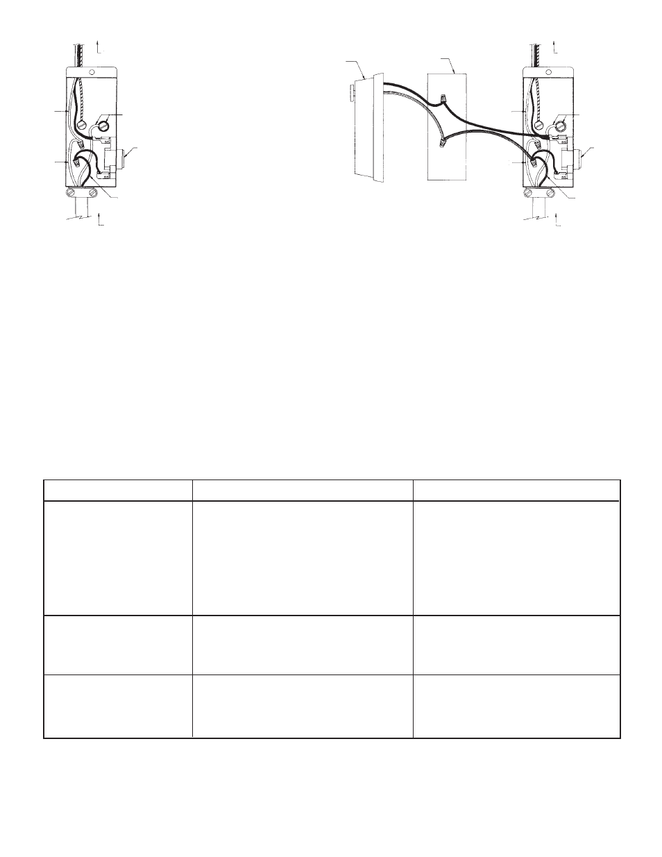
2. For standard installation, connect the two leads in the thermostat/junction box to the two supply leads. Attach ground wire from the supply
to the green ground screw in the box. See Fig. 3.
3. See Figure 4 for wiring dehumidistat to ventilator.
4. Replace cover to thermostat/junction box.
5. The ventilator will automatically turn “ON” when the attic temperature rises above 105º F and will turn “OFF” when the temperature drops
below 95º F.
FIG. 3
FIG. 4
WHITE
GROUND
WHITE
THERMOSTAT
BLACK
120 VOLT
SUPPLY
TO MOTOR
DEHUMIDISTAT
JUNCTION
BOX
WHITE
GROUND
WHITE
THERMOSTAT
BLACK
120 VOLT
SUPPLY
TO MOTOR
WARNING: The motor is thermally protected and automatically temperature controlled and may start without warning; therefore,
make certain that the power source is disconnected before attempting to service or disassemble any components! If the power
disconnect is out of sight, lock it in the open position and tag to prevent application of power.
TROUBLE SHOOTING CHART
WARNING: Items marked with an asterisk (*), should be performed only by experienced and qualified personnel.
Excessive noise
1. Propeller blade contacting housing
1. Realign or replace
2. Foreign material inside housing
2. Clean
3. Motor loose
3. Secure properly
4. Motor needs oiling
4. See lubrication
5. Dirt accumulation on propeller, causing
5. Clean
imbalance
Insufficient air flow
1. Not enough eave vents to provide
1. See Installation
“make-up” air
2. Clogged screen
2. Clean or replace
Unit fails to operate
1. Blown fuse or open circuit breaker
* 1. Replace fuse or reset circuit breaker
2. Motor
* 2. Replace
3. Thermostat
* 3. Replace
SYMPTOM
POSSIBLE CAUSES
CORRECTIVE ACTION
LUBRICATION: To prolong the life of the motor, oil motor every six months of use with S.A.E. 20 Motor Oil.