Installation in existing homes – Qmark MM667ICF - Compact Bath Fan User Manual
Page 3
INSTALLATION IN EXISTING HOMES
1.
Review the section: “New Home Installation” and follow directions where applicable.
2.
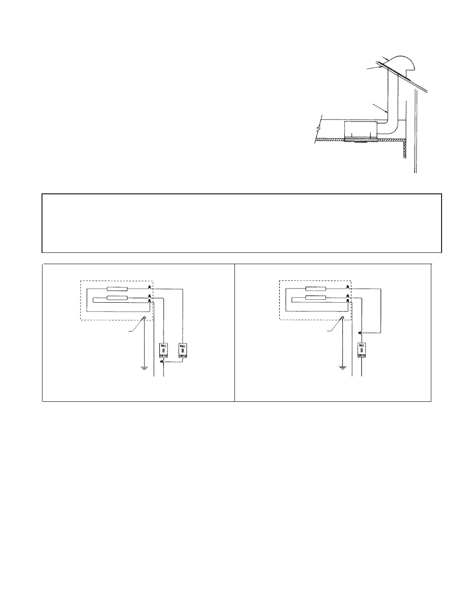
Refer to wiring diagrams for wiring and Fig. 4 and 5 for duct work.
3.
Determine location of ventilator, remembering that the housing must be installed next to a joist.
4.
Drill a small hole in ceiling in proposed location, then locate this hole in the attic.
5.
In the attic, position housing against ceiling joist and over drilled hole. Using the housing as a template, mark ceiling
for cutout. Make cutout on this line.
6.
Remainder of the installation is the same as steps 1 through 8 under “New Home Installation” above. Cracks between
housing and ceiling may be plastered or caulked.
OUTLET BOX
RECEPTACLES
VENTILATOR
BLACK
BLACK
WHITE
WHITE
GROUND SCREW
GROUND
BLACK
BLACK
BLACK
WHITE
WIRING DIAGRAM
MODEL A6641C
WIRING DIAGRAM
MODEL A6641C
WITH (1) ONE SWITCH
LIGHT
WHITE
BLACK
OUTLET BOX
BLACK
BLACK
BLACK
LIGHT
VENTILATOR
WHITE
GROUND SCREW
GROUND
RECEPTACLES
WHITE
BLACK
120V AC
60 HZ
SUPPLY
120V AC
60 HZ
SUPPLY
-3-
CAUTION:
BE SURE ALL WIRING COMPLIES WITH LOCAL AND NATIONAL ELECTRICAL
CODES.
AND HOUSING IS PROPERLY GROUNDED.
FIG. 5
ROOF CAP
ROOF
ROUND
DUCT
5. Use appropriate size duct for best performance. Model
A664IC uses 4” duct.
IMPORTANT: Be sure nothing obstructs the discharge of the
fan. Take precautions to ensure that insulation does not get
into duct work or fan discharge opening.
6. Remove lens from grille. Insert tabs on reflector into
notches in grille. Slide reflector onto grille until tabs lock
into place. See Fig. 1.
7. Place light plug into receptacle. Align the center hole in
the reflector with the threaded screw hole in the grille
mounting bracket. Fasten the screw supplied. See Fig. 1.
8. Install type A-19, 100 watt light bulb (max.) and replace
lens.