New home inst alla tion, Inst alla tion in existing homes, Fig. 4 fig. 5 fig. 6 – Qmark MM647B Economy Quick Mount Bath Fans User Manual
Page 2
NEW HOME INST
ALLA
TION
1.
Carefully remove unit from carton. Place grille in a safe location until needed. Remove ship-
ping tape from air discharge backdraft damper
.
2.
Position housing against joist. Housing is stamped to show a line at 3/4” for standard
sheetrock and plaster and 3/8” for drywall. (See Figs. 2 & 3). Drive pre-assembled screws on
mounting brackets to secure housing.
There are two tabs opposite each mounting bracket to
provide additional support. If the unit is mounted for 3/8” clearance, the small tab remains in
place. If mounted for 3/4” clearance, the smaller tab is bent out of the way to expose the larger
box.
3.
Run 120V
AC, 60Hz power leads from wall switch or Model 101
1 timer to appropriate knockout
in housing. Use a BX of Romex connector on outlet box.
4.
Remove outlet box cover by pulling downward while simultaneously pushing in side of cover
at indicated point to release locking tab. Connect wire from wall switch to motor wire using
approved wire connectors - white to white, black to black. Remove grounding clip and insert
ground wire. (See Fig. 6) Push or tap clip into notch in housing. Cut of
f excess ground wire.
Replace outlet box cover insuring locking tab is engaged.
-2-
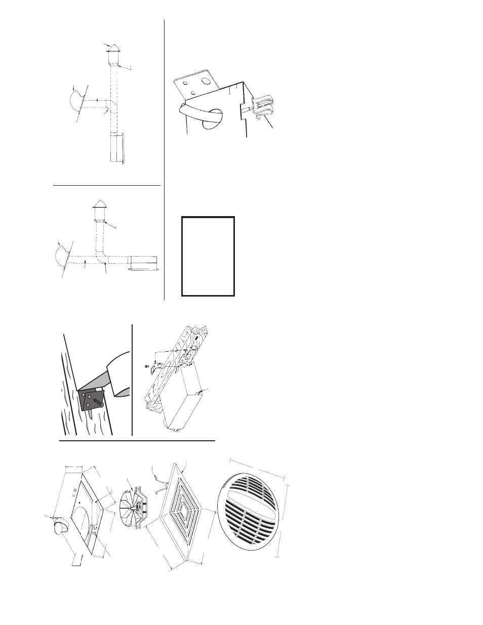
5.
Run three-inch round duct from ventilator air discharge outlet to wall or roof cap . (See
Fig.
4
&
5.)
IMPORT
ANT
: BE SURE NOTHING OBSTRUCTS THE DISCHARGE OF THE F
AN. T
AKE
PRECAUTIONS T
O ENSURE THA
T INSULA
TION DOES NOT GET INT
O THE DUCT WORK
OR F
AN DISCHARGE OPENING.
6.
Install grille by Squeezing springs and inserting into tabs located in housing. See Fig. 1. Press grille
firmly inplace.
INST
ALLA
TION IN EXISTING HOMES
1.
Review “New Home Installation” above and follow all instructions where applicable.
2.
Refer to Fig. 4 &
5 for duct work.
3.
Determine proposed location of fan, remembering that the housing must be installed next
to joist.
4.
Drill a small hole in ceiling in proposed location, then locate this hole in the attic.
5.
In the attic, position housing against ceiling joist and over drilled hole. Using the housing as
a template mark ceiling for cutout. Make cutout on this outline.
6.
Remainder of the installation is the same as steps 1 thru 6 under “New Home Installation”
above.
Any cracks between housing and ceiling may be plastered or caulked.
CAUTION
Be sure all wiring
complies with Local and
National Electrical Codes
and housing is properly
grounded.
FIG. 1
FIG. 2
FIG. 3
FIG. 4
FIG. 5
FIG. 6
AIR DISCHARGE
OUTLET
KNOCKOUT
SUPPOR
T
MOUNTING
T
ABS
3” ROUND
DUCT
3” ROUND DUCT
ADJUSTABLE
ELBOW
ADJUSTABLE
ELBOW
MODEL 1117A
WALL
CAP
MODEL 1117A WALL CAP
IN WALL
IN CEILING
MODEL AD1106 ROOF CAP
MODEL AD1106 ROOF CAP
REDUCER FURNISHED
WITH WALL CAP
REDUCER FURNISHED
WITH WALL CAP
OUTLET
BOX
MOT
OR &
BRACKET
ASSEMBL
Y
SPRING CLIP
GRILLE
8
5
⁄
8
”
9
5
⁄
8
”
6
13
⁄
16
”
7
13
⁄
16
”
GRILL
MTG T
ABS
3
3
⁄
4
”
3
⁄
4
3
⁄
8
12
1
⁄
4
”
10
3
⁄
4
”
MM647B
A647B
Note:
Duct adapter may be installed at factory
.
Remove tape from duct door before use.
DUCT
ADAPTER