2 identifying fault codes and recovering, Table 6.3 - list of fault codes, D 6.3. a – Carrier D2-3466-2 User Manual
Page 26
6-8
Carrier VFD Quick Reference
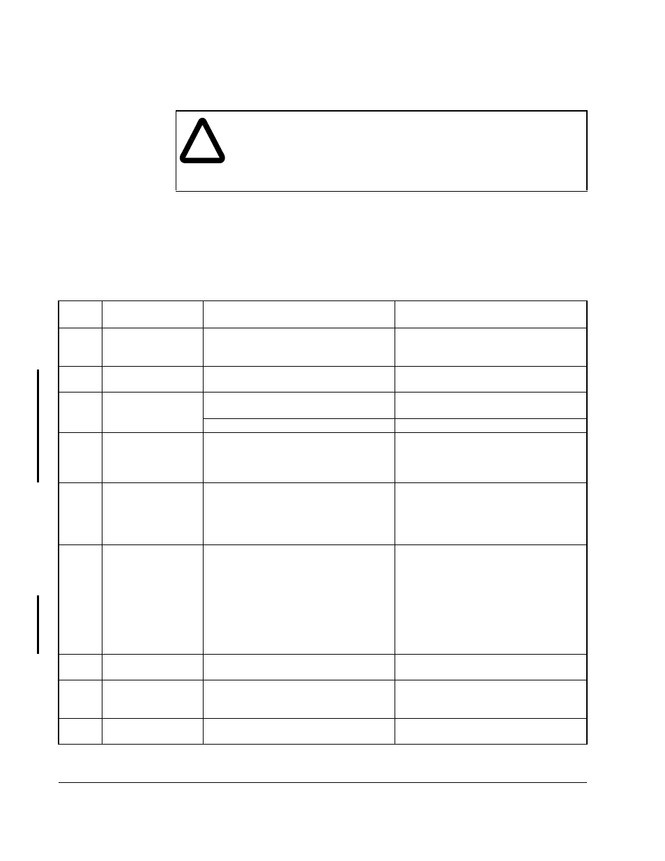
6.4.2 Identifying Fault Codes and Recovering
Drive fault codes are shown in table 6.3. To clear a single fault that has occurred so
that the drive can be started again, correct any problems indicated by the fault code
and press the STOP/RESET key on the keypad, or assert the fault reset from the
selected control source (P.000). Because multiple faults can occur and only the first
will be displayed, you must access the error log in order to view all of the faults that
have occurred. See section 6.4.3 for instructions on how to view the error log.
!
ATTENTION: DC bus capacitors retain hazardous voltages after input
power has been disconnected. After disconnecting input power, wait five
minutes for the DC bus capacitors to discharge and then check the
voltage with a voltmeter to ensure the DC bus capacitors are discharged
before touching any internal components. Failure to observe this
precaution could result in severe bodily injury or loss of life.
Table 6.3 – List of Fault Codes
Code
Fault
Description
Fault Cause
Corrective Action
AIn
Analog input signal
loss
P.011 = 4 or 5 and 4 to 20 mA analog
input is below 1 mA.
Verify that P.011 is set correctly.
Check that the analog input source
supply
≥1 mA.
bYC
Incorrect precharge
status
Precharge initiated and incorrect
precharge status is returned.
Check operation of the precharge.
CHS
Default parameter
restore (checksum
error)
During drive operation:
Regulator board failure.
Contact Reliance or replace Regulator
board.
After Regulator board replacement:
Contact Reliance.
EC
Earth current failure
(ground fault)
Unintentional grounding of the input.
Check isolation between ground and
output terminals. Possible leakage,
current sensor defects; replace
sensor.
EEr
Non-volatile
memory write
failure
Failure on write to non-volatile
memory.
Connect CS3000 software to upload
parameters or record by hand. Then
replace Regulator board. Parameter
values will be lost when power is
cycled.
EL
Encoder loss
Drive is not detecting feedback from
the encoder.
For SVC operation, conditions exist for
more than 5 seconds that may result in
an inability to complete a ramp-to-rest
stop.
Check the connection between the
encoder and the drive. Check the
encoder/motor coupling.
For SVC operation, check motor data
parameters. Check U.006. Incorrect
magnetizing current may be generated
by performing self-tuning with a load
connected to the motor.
FL
Function loss
Function loss input on control terminal
is opened.
Check external interlocks at terminals
16, 20.
HId
High time
identification
aborted
Identification process for V/Hz has
been aborted.
See H.019 for identification result.
HIL
High line voltage
Input voltage more than 15% above
nominal.
Check actual line voltage against
U.018 or H.021.