Palmrest assembly, Removing the video graphics board, Replacing the video graphics board – Dell Latitude C810 User Manual
Page 19: Removing the palmrest assembly
Removing the Video Graphics Board
1.
Follow the instructions in
"Preparing to Work Inside the Computer
."
2.
.
3.
4.
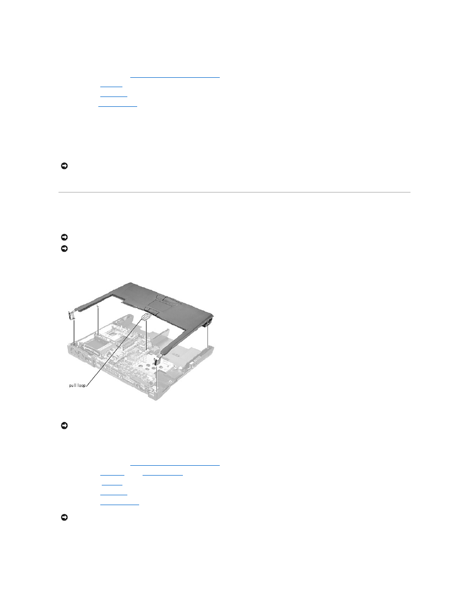
Detach the
from the strain relief and the graphics card.
5.
Remove the three 8-mm screws that secure the video graphics board.
6.
Separate the video graphics board from the system board connector.
Replacing the Video Graphics Board
1.
Align the three screw holes and press down firmly on the word "Dell" to seat the board in its connector.
2.
Replace the three screws.
Palmrest Assembly
Palmrest Assembly
Removing the Palmrest Assembly
1.
Follow the instructions in
"Preparing to Work Inside the Computer
."
2.
3.
Remove the
.
4.
5.
.
6.
Turn the computer over.
7.
Remove the nine 20-mm screws (labeled with a "circle P") that secure the palmrest to the computer.
NOTICE:
Make sure the board is correctly and firmly seated before continuing. Failure to do so will cause intermittent video failures.
NOTICE:
Disconnect the computer and attached devices from electrical outlets and remove any installed batteries.
NOTICE:
To avoid ESD, ground yourself by using a wrist grounding strap or by periodically touching unpainted metal on the computer.
NOTICE:
The reserve battery provides power to the computer's time RTC and NVRAM when the computer is turned off. Removing the palmrest
disconnects the reserve battery and causes the computer to lose the date and time information as well as all user-specified parameters in NVRAM. If
possible, make a copy of this information before you disconnect the reserve battery.
NOTICE:
To avoid damaging the palmrest assembly, you must first remove the display assembly.