Brake pedal and parking brake pedal, Parking brake pedal, Drive handles – Cub Cadet 365 User Manual
Page 9: Speed control bar
9
•
Battery: The BATTERY indicator light will
illuminate any time the ignition key is in the ON
position and the engine is not running. If it
illuminates while the engine is running, then the
battery is in need of a charge. Refer to the
MAINTENANCE section of this manual for the
proper battery charging procedure.
•
Temperature: (Liquid Cooled Models Only) Stop
the engine immediately. Check clean air intake and
cooling areas.
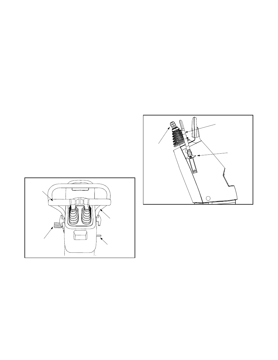
Brake Pedal and Parking Brake Pedal
The brake pedal is located on the lower left side of the
control tower and it is used to engage the brake in order
to slow down or stop the unit. It also is used to engage
the parking brake. See Figure 1 and Figure 7.
Parking Brake Pedal
The parking brake pedal is located on the lower right
side of the control tower. Engage the parking brake
when the unit is not in use. See Figure 7.
•
Push down on the brake pedal and hold.
•
Push down on the parking brake pedal and hold.
•
Release brake pedal to lock parking brake
engagement.
•
To release parking brake pedal, press down on
brake pedal and release.
Figure 7
Drive Handles
The drive handles (left and right) are located at the top
of the control tower. The drive handles are used to
move, steer, and stop the Z-Series. The drive handles
will return toward the neutral position when released;
however, the driver should place the drive handles in
the neutral position so the unit will not move. If the drive
handles are not placed in the neutral position, the Z-
Series may creep. See Figure 1 and Figure 7.
When the engine is running, the unit will move in
accordance with the drive handles (push, pull, or both)
as they are moved from the neutral position. When the
drive handles are released, they immediately return
towards the neutral position as the unit slows to a stop
position (while the engine continues to run).
The rear wheels move and steer the unit. The left drive
handle controls the left rear wheel and the right drive
handle controls the right rear wheel. When a drive
handle is moved forward, the respective wheel turns
forward. When a drive handle is moved backward, the
respective wheel turns in reverse.
Each drive handle has a range in the forward position
(push) and the reverse position (pull). The drive
handles can be moved together in the same direction or
independent of each other in any combination (i.e. left
push, right pull). refer also to the Quick Reference
OPERATION section. See Figure 8.
Figure 8
Speed Control Bar
The speed control bar is connected to the console with
two wing nuts and it is used as a grab bar for entry or
exit from the tractor and allows for pre-set maximum
travel speed. See Figure 1 and Figure 8.
•
Loosen the wing nuts located on either side of the
plastic console.
•
Rotate speed control bar to desire location.
•
Tighten wing nut to secure speed control bar.
NOTE: Limit loosening the wing nuts to 1 1/2 turns. This
will insure proper assembly of the screw not visible on
the other side of the plastic console.
The speed control bar also aids the drive handles in
making “perfect U-turns”. To move forward grasp both
drive handles and the speed control bar at the same
time, then release the left drive handle to turn left and
then grasp it again to continue straight ahead or release
the right drive handle to turn right. Refer also to the
Quick Reference Chart located in the OPERATION
Section.
Brake
Pedal
Parking
Brake Pedal
Drive
Handle
Speed
Control Bar
Wing Nut
Speed Control
Bar
Drive
Handles