2 setup – Crown Audio CE Series User Manual
Page 10
Operation Manual
CE Series Power Amplifiers
page 10
2 Setup
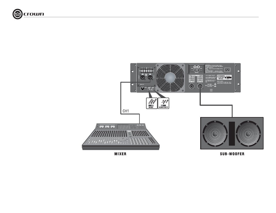
Figure 2.11 Typical System Wiring, Bridge-Mono Mode
2.6.3 Bridge-Mono Mode
Make sure the amplifier is turned off and the
level controls are turned down before you wire
the system.
Typical input and output wiring is shown in
Figure 2.11.
INPUTS: Connect input wiring to CH 1.
OUTPUTS: Connect the speaker across the posi-
tive (+) output terminals. Do not use the negative
(–) terminals when the amplifier is being oper-
ated in Bridge-Mono mode. Refer to Section 2.5
for output connector pin assignments. Make
sure the Mode switch is set to the “Bridge” posi-
tion when operating in Bridge-Mono mode.
NOTE: Turn down (full CCW) the Channel
2 level control when operating the
channel pair in Bridge-Mono mode, as
the Channel 1 level control works both
channels.
NOTE: Crown provides a reference of wiring pin
assignments for commonly used connector
types in the Crown Amplifier Application Guide
available at www.crownaudio.com.
- MT-2400 (1 page)
- XTi 4000 (44 pages)
- 402and 602 (28 pages)
- DSi 4000 (1 page)
- S Series (28 pages)
- CTs 4200 USP/CN (2 pages)
- CH3 (2 pages)
- MA-5000i (52 pages)
- Commercial Audio Series (180MA-280MA-1160MA) (24 pages)
- Pulse 21100 (22 pages)
- Pulse 2X1100 (1 page)
- K2 (2 pages)
- XLS-602 E (1 page)
- Macro-Tech 602 (36 pages)
- I-TECH 8000 (2 pages)
- 660A (1 page)
- 5000i (1 page)
- MT 600 (1 page)
- 28M (1 page)
- PT 2.1 (2 pages)
- CTs 8200 USP/CN (2 pages)
- SR-II (1 page)
- CTs 2000 (1 page)
- 4300 (1 page)
- IQ-PIP USP3/CN (2 pages)
- 180A (1 page)
- XLS 402 (40 pages)
- 9000i (1 page)
- I (1 page)
- CL2 (1 page)
- MA-2402 (36 pages)
- CROWN K Series (20 pages)
- M Series (28 pages)
- CE 2000 (28 pages)
- Power Tech x.1 Series (24 pages)
- XTi 1000 (2 pages)
- XLS-802 (1 page)
- D-45 (24 pages)
- Xs1200 (28 pages)
- MA-24X6 (32 pages)
- I-T4000 (1 page)
- CTs 600 (32 pages)
- 12000i (2 pages)
- CDi 4000 (1 page)
- MA-3600VZ (28 pages)