Feedback – Cypress CY8C29x66 User Manual
Page 15
AN2309
November 25, 2007
Document No. 001-17394 Rev. *B
- 15 -
The minimum cell-balance parameter consists of the voltage measure error value plus the internal impedance error value.
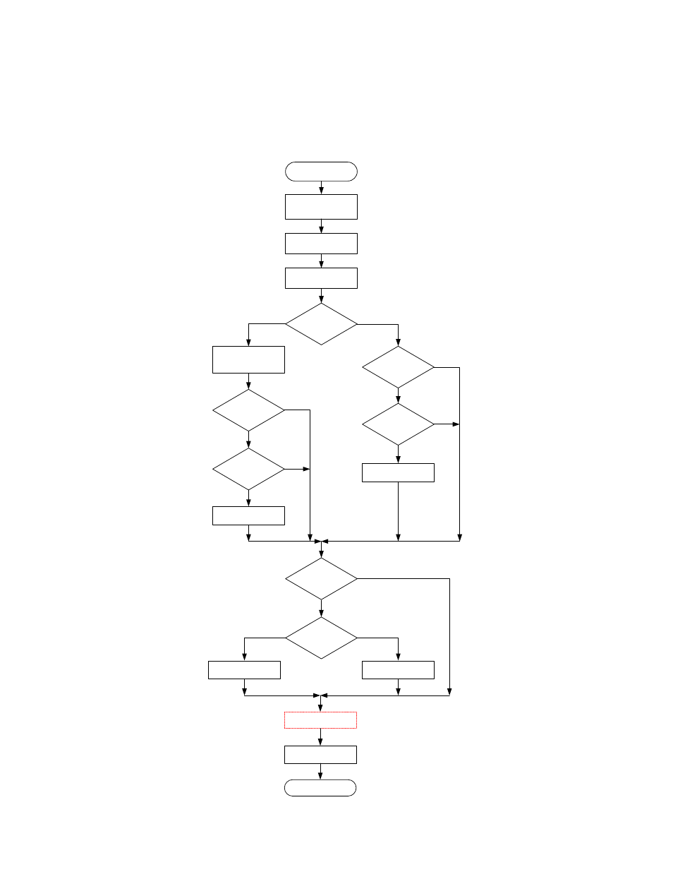
The cell-balancing algorithm that is implemented here does not significantly lengthen the charge time. The charger monitors all
of the cell voltages. Cell balancing is performed during both phases and it is realized in one common module. The cell-
balancing algorithm is represented in
Figure 11
. The cell-balancing profile examples are shown in the Appendix,
Figure 11. Cell-Balancing Algorithm
Start
Chagre Off
Balancing Reset
DoCellBalancing = FALSE
Wait Start Delay
Send Debug Data
Are cells Not
Balanced?
V
bmax
-V
bmin
>dV
ch_balmin
No
Measure V
b1
, V
b2
Calc V
bmin
, V
bmax
, dV
Check Out Of The
Minimum Cell
Balancing Current
isCV and I
ch
balmin Yes No Yes End Chagre On Wait End Delay Is Discharge State? No Yes Are Cells Not Balanced? V bmax -V bmin > dV disch_balmin No Check Out Of The VMID Voltage V bmax mid Yes No DoCellBalancing = TRUE Yes DoCellBalancing = TRUE Is DoCellBalancing? Yes V b1 >V b2 Yes No Balancing Cell 1 Balancing Cell 2 No