Defiant 1610ce non-catalytic woodburning stove, Install the optional ash door heat shield, Adjust the leg levellers – Vermont Casting 1610CE User Manual
Page 13: Reverse the flue collar (if necessary), Attach the damper handle, Attach the primary air thermostat handle, Assemble the removable insert handle, Fan kit installation
13
Defiant 1610CE Non-Catalytic Woodburning Stove
30003846
Install the Optional Ash Door Heat Shield
Many installations will require the use of the supplied
ash door heat shield. Refer to the “Floor Protection”
sections starting on Page 9 to determine if your installa-
tion requires the use of the ash door heat shield.
1. Remove the two Phillips pan head screws from the
ash door.
2. Insert the screws through the ash door heat shield
(from the painted side), place the 8 mm (5/16”)
spacers over the screws, and carefully thread them
back into the original holes. (Fig. 21) The curved lip
should be upward, under the ashlip of the stove.
3. Tighten securely.
ST539
Attach
ash door
heat shield
11/00
ST538
Spacers
Fig. 21 Install the ashdoor heat shield.
Adjust the Leg Levellers
Lift the stove slightly so there is no weight on the leg
while making the adjustment.
Reverse the Flue Collar (If necessary)
Reverse the flue collar by removing the two screws that
attach it to the back of the stove. Be sure the gasket
around the flue collar opening is in position when you
screw the collar back onto the stove.
Attach the Damper Handle
Use the 1/4” -20 x 3” screw to attach the damper handle
to the damper stub on the left side.
Attach the Primary Air Thermostat Handle
The primary air thermostat handle is the smaller of the
two black handles. Secure the handle to the stub on
the right side of the stove with an 8-32 x 2” slot head
machine screw. (Fig. 22)
Assemble the Removable Insert Handle
The ceramic removable insert handle opens and closes
the front doors. Remove after each use, and store it in
the handle holder behind the right front leg. Assemble
the handle by passing the 86 mm (3³⁄₈") screw through
the ceramic shaft and into the bright metal nub. (Fig. 23)
Tighten carefully until snug.
ST540
Assembly
handle
11/00
ST540
Fig. 23 Assemble the front door handle.
DEFIANT
ST539
attach
thermostat
handle
11/00
ST539
Fig. 22 Attach the thermostat handle.
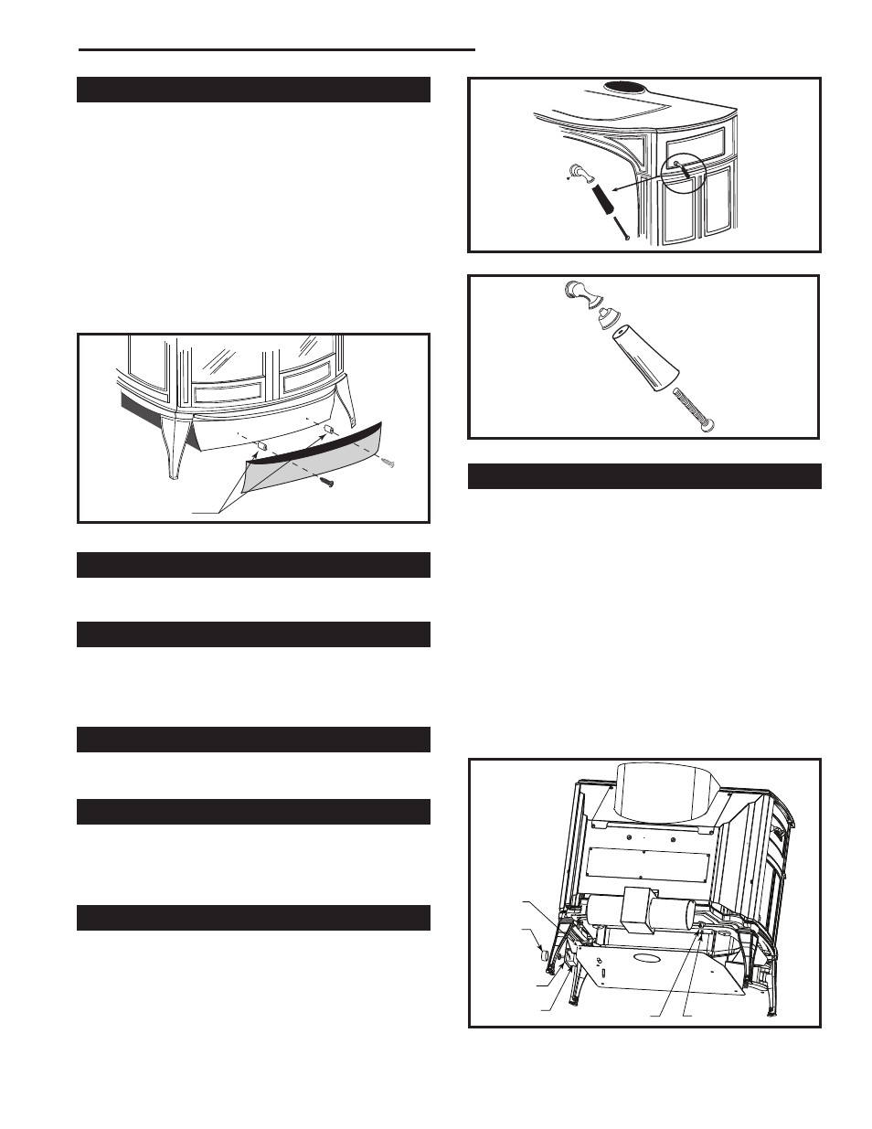
Fan Kit Installation
1. Attach the fan assembly at the bottom edge of the inner
back with two (2) 1/4-20 x 3/4” hex head screws.
2. Attach snapstat to the mounting holes on the underside
of the bottom with two (2) 1/4-20 pan head screws.
3. Attach the rheostat holder (provided with the stove)
under the right front wing of the bottom heat shield with
two (2) #10 sheet metal screws.
4. Attach the rheostat to its holder by inserting the rheo-
stat control shaft through the holder hole. Install the
retaining ring and rheostat knob onto the shaft.
5. Secure the rheostat cable to the underside of the bot-
tom heat shield using the wire tie provided and the hole
at the right rear edge of the heat shield.
6. Fan will not operate until stove reaches approximately
43° C (109° F).
Fig. 24 Fan installation (Kit # 2767).
�����
�����������
����
Rheostat
Knob
Rheostat
Snapstat
Screws
ST848
Hole for Wire
Tie to Secure
Cable
Rheostat
Holder