Baumer SXG cameras User Manual
Page 2
Data Interfaces
Data / Control
1000 Base-T (Port 0)
Data / Control
1000 Base-T (Port 0)
LED2
LED1
8
1
LED2
LED1
8
1
1
(gn/wh)
MX1+
1
(gn/wh)
MX1+
2
(gn)
MX1-
2
(gn)
MX1-
3
(og/wh)
MX2+
3
(og/wh)
MX2+
4
(bu)
MX3+
4
(bu)
MX3+
5
(bu/wh)
MX3-
5
(bu/wh)
MX3-
6
(og)
MX2-
6
(og)
MX2-
7
(bn/wh)
MX4+
7
(bn/wh)
MX4+
8
(bn)
MX4-
8
(bn)
MX4-
Notice
Both data ports supports Power over Ethernet (38 VDC .. 57 VDC).Both ports can
be connected to a PoE power sourcing equipment however only one port will be
used to power the camera.
For the data transfer, the ports are equal. For Single GigE connect one port and
for Dual GigE connect the second Port additionally. The order does not matter.
Power Supply and Process Interface
Power Supply
Digital I/O-Supply
M8 / 8 pins
1
4
3
8
5
7
3
1
4
2
6
1
(bn)
Power V
CC
1
(wh)
Line 5
3
(bu)
GND
2
(bn)
Line 1
4
(bk)
not used
3
(gn)
Line 0
4
(ye)
GND
5
(gr)
U
ex
6
(pk)
Line 3
7
(bu)
Line 4
8
(rd)
Line 2
Power Supply
Power VCC
20 VDC .. 30 VDC
LED Signaling
1
2
3
LED
Signal
Meaning
1
green
green flash
Link active
Receiving
2
yellow
Transmitting
3
green
qellow
Power On
Readout active
Heat Transmission
Caution
Provide adequate dissipation of heat, to ensure that the temperature
does not exceed +60°C (+140°F).
The surface of the camera may be hot during operation and immediately
after use. Be careful when handling the camera and avoid contact over a
longer period.
T
T
T: Housing temperature
measurement point
As there are numerous possibilities for installa-
tion, a specific method for proper heat dissipation
is not defined, but the following principles are
suggested:
Operate the cameras only in mounted condition
▪
with a good heat conductor (e.g. aluminum)
Mounting in combination with forced convection
▪
may provide proper heat dissipation
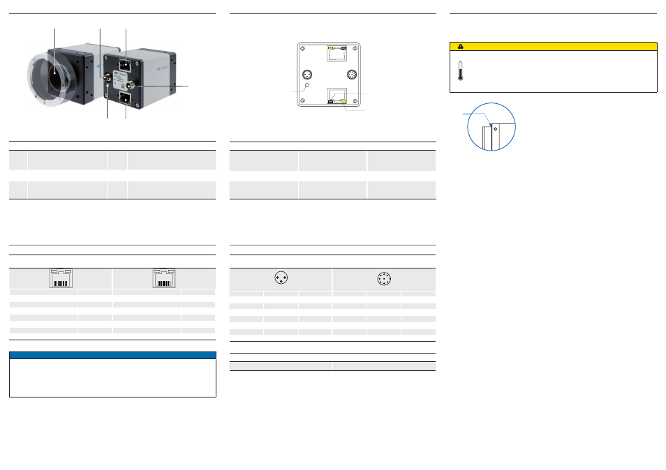
General Description
1
2
3
4
5
6
Nr.
Description
Nr.
Description
1
(respective) lens mount
4
Digial-IO supply
2
Power Supply
5
Data Port 1
3
Data Port 0
6
Signaling-LED