Baumer HXG cameras User Manual
Page 2
LED Signaling
1
2
3
LED
Signal
Meaning
1
green
green flash
Link active
Receiving
2
yellow
Transmitting
3
green
yellow
Power On
Readout active
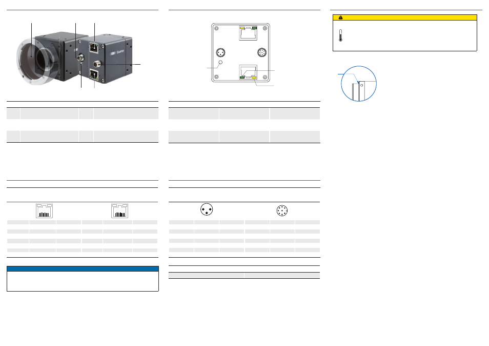
General Description
1
2
3
4
5
6
No.
Description
No.
Description
1
(respective) lens mount
4
Digial-IO
2
Power Supply
5
Data Port 2
3
Data Port 1
6
Signaling-LED
Heat Transmission
Caution
Provide adequate dissipation of heat, to ensure that the temperatu-
res does not exceed +50°C (+122°F).
The surface of the camera may be hot during operation and imme-
diately after use. Be careful when handling the camera and avoid
contact over a longer period.
T
T
T: Housing temperature
measurement point
It is very important to provide adequate dis-
sipation of heat, to ensure that the housing
temperature does not reach or exceed +50°C
(+122°F). As there are numerous possibilities for
installation, a specific method for proper heat dis-
sipation is not defined, but the following principles
are suggested:
Operate the cameras only in mounted condition
▪
with a good heat conductor (e.g. aluminum)
Mounting in combination with forced convection
▪
may provide proper heat dissipation
Data Interfaces
Data / Control
1000 Base-T (Port 1)
Data / Control
1000 Base-T (Port 2)
wire colors of the connecting cable
LED2
LED1
8
1
LED2
LED1
8
1
1
green/white
MX1+
1
green/white
MX1+
2
green
MX1-
2
green
MX1-
3
orange/white MX2+
3
orangeg/white MX2+
4
blue
MX3+
4
blue
MX3+
5
blue/white
MX3-
5
blue/white
MX3-
6
orange
MX2-
6
orange
MX2-
7
brown/white
MX4+
7
brown/white
MX4+
8
brown
MX4-
8
brown
MX4-
Notice
Data port 1 supports Power over Ethernet (38 VDC .. 57 VDC).
For the data transfer, the ports are equal. For Single GigE connect one port and
for Dual GigE connect the second port additionally. The order does not matter.
Power Supply and Process Interface
Power Supply
Digital I/O
M8 / 8 pins
wire colors of the connecting cable
1
4
3
8
5
7
3
1
4
2
6
1
brown
Power V
CC
1
white
Line 5
3
blue
GND
2
brown
Line 1
4
black
not used
3
green
Line 0
4
yellow
GND
5
grey
U
ex
6
pink
Line 3
7
blue
Line 4
8
red
Line 2
Power Supply
Power V
CC
20 VDC ... 30 VDC