CompuSTAR CM4000 User Manual
CompuSTAR Car alarm
IMPORTANT: All CM4000 Control Modules need firmware updates to be 2 Way Datalink compatible. Check CompuStar.com for the latest firmware updates.
CM4000 Alarm/Starter Control Module Installation Manual
This manual is for authorized CompuStar Pro dealers. Please thoroughly review this manual before beginning installation. If
you have any questions please contact your distributor or tech support 888-820-3690. (8:00 am to 5:00 pm Pacific Coast Time)
This is a simplified manual. The Master Installation Manual is available on www.compustar.com.
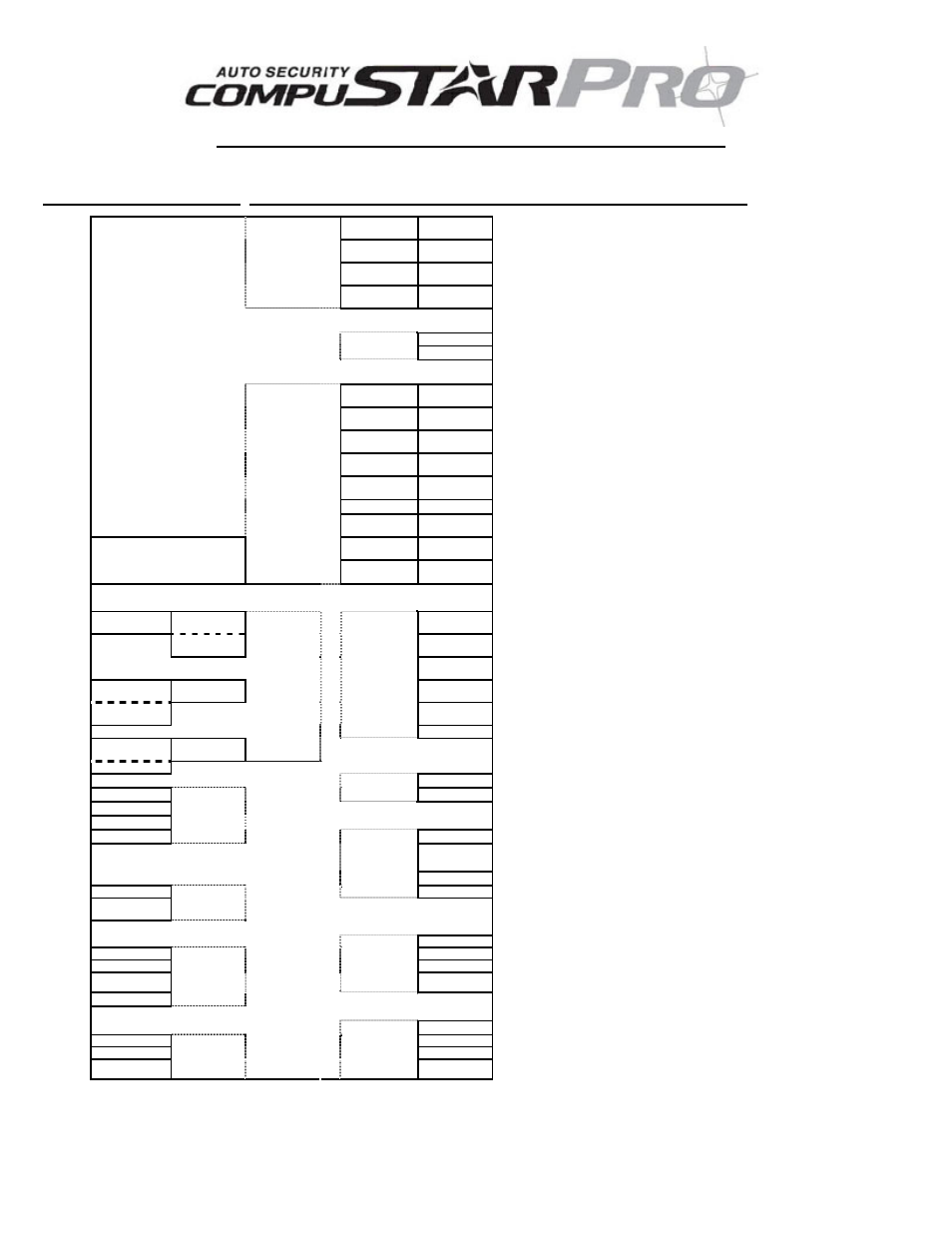
1 Red
2 Green /
White
1: ( + ) 12v Constant
2: ( + ) Parking Light
3 Red / White
4 White
3: ( + ) 12v Constant and Red/White prewired to
2
nd
Relay
4: ( + ) Accessory
5 Violet
6 Yellow
5: ( - ) When Armed prewired to Starter Kill
Relay
6: ( + ) Starter prewired to Starter Kill Relay
CN1
7 Green and
Red
8 Black
7: ( + ) Ignition and Red prewired to Starter Kill
Relay
8: ( - ) Ground
1 Red
1: ( + ) 12v Back Up Battery
CN2
2 Black
2: ( - ) Ground Back Up Battery
1 Green /
White
2 Lt Blue
1: ( - ) Parking Lt. Output – POC 1
2: ( - ) E-Brake Input
3 Red / Black
4 Lt. Blue /
White
3: ( - ) Starter Output – POC 2
4: ( + ) Brake Input
5 Green
6 Violet /
Black
5: ( - ) Ignition Output – POC 3
6: ( - ) Trunk Input
7 White /
Black
8 Red / White
7: ( - ) Accessory Output – POC 4
8: ( - / + ) Door Input
9 Black
10 Brown /
White
9: ( - ) Status Out (GWR) – POC 5
10: ( - ) Glow Input/Key Sensing
11 Orange
12 Pink
11: ( - ) Rearm Output – POC 6
12: ( - ) Slave/Closed Loop Input
13 Orange /
White
14 Yellow /
Black
13: ( - ) Disarm Output – POC 7
14: (AC) Tach / Alternator Input
Green/White
Loop
15
White
16 Gray /
Black
15: ( - ) Horn Output – POC 8
16: ( - ) Hood Input
Cut=Auto Trans. Uncut=Manual
Trans.
CN3
17 Violet
18 Brown
17: ( - ) Dome Light – POC 9
18: ( + ) Siren Output
( + )
( - )
None
Future use
Door Trigger
Polarity
Default
2 Violet /
White
( - ) Trunk release output
3 Orange /
Black
( - ) Second Unlock Output
( + )
( - )
4 Blue
( - ) Unlock Output
Key
Sense/Glow
Plug Polarity
Default
5 Blue / Black
( - ) Lock Output
CN4
None
( + ) 12v Constant Power
( + ) Parking
Lights
Trunk
Release
Jumpers
Behavior of
CN1, Pin 2
Default
Black
LED ( - )
4 ( - )
CN5
LED
Black / White
LED ( + )
3 ( + )
2 Data
1
Data
CN12
RS232
1 Black
( - )
2
White
2nd
Stage
Shock
3 Red
( + )
2 Black
CN6
Shock
Sensor
4 Yellow
1st Stage Shock
1
Black
/
White
CN11
Thermistor
1 Black
( - )
1st Stage
4 Grey / White
2 White
Knock
( + )
3 Red
3 Red
( + )
2nd Stage
2 Black / White
CN7
RPS Sensor
4 Yellow
LED
( - ) GWA
1 Black
CN10
Optional
Sensor Input
1 Black
( - )
( - ) Switch
3 Gray
2 White
( + )
( + ) Led
2 Gray
3 Red
TX
( - ) Led
1 Gray / Black
CN9
Plug In
LED/Valet
Switch
CN8
Antenna
4 Yellow
RX
V.37 Firmware or Greater
Document Outline
- CM4000 Alarm/Starter Control Module Installation Manual
- Setting the RPS (Remote Paging Sensor) Code
- Programming the Secure Valet Code
- Option Programming Using the OP500 Option Programmer
- Option Programming Using a Remote
- Green/White Loop (CM4000 and CM4200DX Models)
- Frequently Asked Questions
- Monday - Friday 888-820-3690
- Email [email protected]
- Web http://www.compustar.com click on “dealer support”