Heat pump connections (single & two-stage), Crestron chv-tstat and chv-thstat thermostats – Crestron electronic CHV-TSTAT User Manual
Page 17
Crestron CHV-TSTAT and CHV-THSTAT
Thermostats
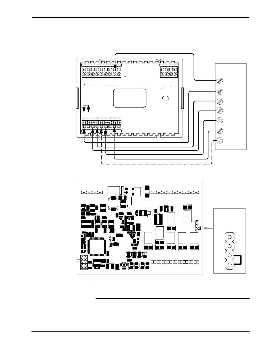
Heat Pump Connections (Single & Two-Stage)
Aux Heat connected to W/W1 – RH and RC jumped together
TOP
HU
M
RH
U
RS
R
RS
R
RS
1
RS
2
24(
C)
24
(R
)
24
V
Y
Z
G
NETWORK
RH
RC
G
Y/
Y
1
Y2
O
B
W/
W
1
W2
Backplate
Jumper
From RH
to RC
Integrated
Control Unit
C
R
Y
G
O
Aux
Y2
(2
nd
Stage)
3
4
P4
Jumper on
P4 pins 3 & 4
Thermostat Circuit Board
CRESTRON ELECTRONICS
P1
P3
P6
P5
P4
1
2
3
4
C
R
G Y Y2 O
Aux
NOTE: For wiring details, refer to the general Heat Pump schematic on the
following page.
Operations and Installation Guide – DOC. 8163B
Thermostats: CHV-TSTAT and CHV-THSTAT
• 13