Wiring diagrams, Crestron chv-tstat and chv-thstat thermostats – Crestron electronic CHV-TSTAT User Manual
Page 13
Crestron CHV-TSTAT and CHV-THSTAT
Thermostats
Wiring Diagrams
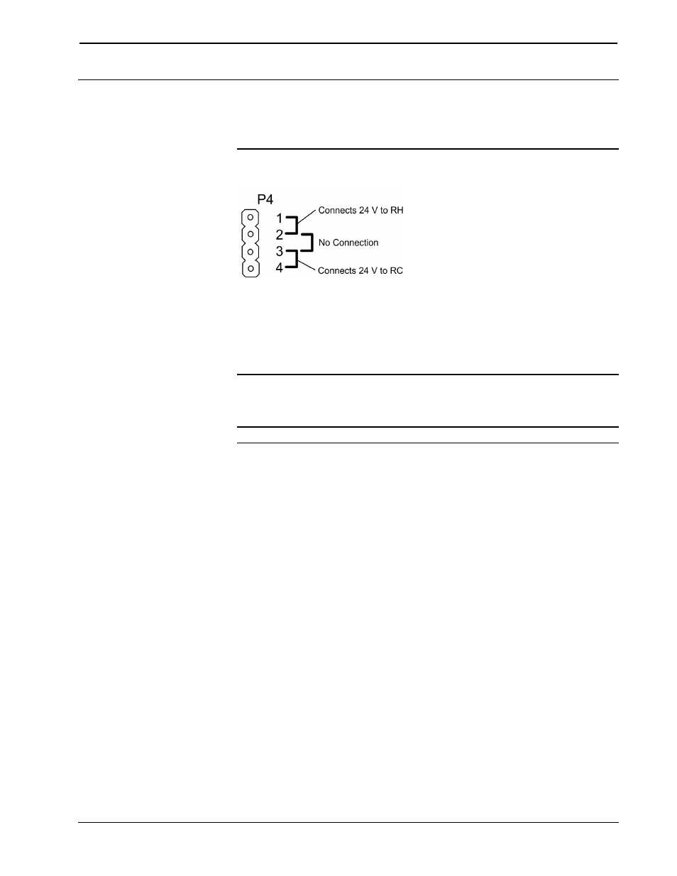
The wiring diagrams that follow show connections for the CHV-TSTAT and CHV-
THSTAT.
CAUTION:
The P4 Jumper Position on the Circuit Board depends on the
power method chosen, and is critical to proper operation. Improper P4 jumper
position can cause equipment damage.
NOTE: Ensure that the power circuits are shut off at the source before connecting
the thermostat. Provide disconnect means and overload protection as required for the
power supply.
NOTE: Ensure that the transformer has sufficient power for all the thermostats in
the system, or use multiple transformers. Refer to the power requirements in
“Specifications” on page 3.
The following diagrams are examples of connections for heat, heat/cool and one-
stage and two-stage heat pump systems.
NOTE: Use either connector O or B as required, for changeover control.
Operations and Installation Guide – DOC. 8163B
Thermostats: CHV-TSTAT and CHV-THSTAT
• 9