Installation instructions, Step b - make tubing connections, Step a - install water supply fittings – EcoPure EPWUFF User Manual
Page 5
5
Installation Instructions
Step B - Make Tubing Connections
NOTE: Remove protective foam plugs before connecting tubes (See Fig. 4). Discard foam plugs.
1. Locate the piece of supplied 3/8" tubing not used previously. Route it between the union connector
and the filter system outlet (See Figures 2 & 3). Allowing some slack, measure and cut to length. Cut
the ends of the tubing square.
2. Insert tubing all the way into the union connector and filter system outlet. Pull on the tubing to be
sure that it's held firmly in the fittings.
3. Repeat steps 1 and 2 to connect the tube installed on the cold water shutoff to the filter system inlet.
Tubing Connection (all push-in fitting locations):
This system includes push-in fittings for quick tubing connections. When working with the fittings, do the
following.
continued on the next page
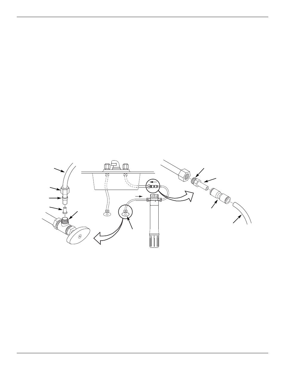
Step A - Install Water Supply Fittings
Check and comply with local plumbing codes as you plan, then install the fittings to connect the
undersink filter into the sink’s cold water supply line. Fittings (9/16-24 thread) and 3/8” O.D. tubing are
included to provide connections to and from the undersink filter’s inlet and outlet. A typical connection
using the included water supply fittings is shown in Figure 3.
1. Close the sink’s water shut off valve(s), or another shut off valve upstream from where you will
install the filter, and open faucets to relieve pressure from the sink’s cold water supply line.
2. Locate the line connecting the cold water shutoff to the sink faucet. Typically this line will be a flexible
hose. Disconnect the nut that connects this line to the cold water shutoff. Use a bucket to catch water
that drains from this line.
3. Locate one piece of the supplied 3/8” tubing, plus the supplied compression nut, ferrule and tubing
insert (See Fig. 3). Assemble the parts onto the tube, as shown in Figure 3, and thread the compres-
sion nut onto the cold water shutoff. Tighten to provide a leak-tight connection.
4. Locate the water supply adaptor (supplied) and, using thread sealing tape, install it into the nut on the
supply line which you disconnected in Step 2. Refer to Figure 3.
5. Press the stem of the water supply adaptor into one end of the supplied union connector (See Figure
3). Be sure to push the stem all the way in.
insert
ferrule
compression
nut
3/8" tubing to
water filter
INLET
use thread
sealing tape
on threads
cold water shutoff
filter system assembly
cold water
shutoff
SINK
filtered water faucet
OUTLET
INLET
water supply
adaptor
flexible connection
to faucet
use thread sealing
tape on threads
3/8" tubing from
water filter
OUTLET
union
connector
FIG. 3