Setup location, Initial setup procedure, Care and preventative maintenance – Drucker Diagnostics Model 642VFD Centrifuge User Manual
Page 4
Setup Location:
1. Unpack the centrifuge and verify that all of the supplied equipment is present.
2. Choose a setup location which meets the following criteria:
a) A bench top clearance height of 20” is required in order to open the lid.
b) The clearance envelope is the space around the centrifuge which is
required for safety. Choose a setup location which will allow for a
clearance envelope of at least 24” x 24”, (with the centrifuge at the center).
No person or hazardous material shall be permitted in the clearance
envelope during operation. The operator time within the envelope shall
be limited to the time necessary for loading, unloading and centrifuge
operation only.
c) Proper ventilation is necessary to prevent the overheating of samples as
well as premature failure of the centrifuge. Choose an area which will
allow unencumbered air flow.
d) The centrifuge is designed to secure to the operating surface by four
suction feet. No adjustment is necessary for leveling the centrifuge,
however, the surface should be flat and level.
e)
Be sure the outlet is always within reach as the line cord is the
means
of
emergency
disconnection!
Initial Setup Procedure:
If any problems are found during the initial setup procedure, refer to the
troubleshooting section on page 10.
1. Plug the female end of the line cord into the rear of the centrifuge. Plug the male
end into an approved ......electrical outlet. For electrical safety, the unit must
always be properly grounded.
2. For safety purposes, the locking system is always activated. To deactivate the
system, (in order to insert or retrieve samples), press the ‘OPEN / STOP’ button
on the control panel. The ‘UNLOCKED’ indicator light should illuminate. If it does
not, refer to page 10 on troubleshooting. The lid will be unlocked for 15 seconds
after pushing the ‘OPEN / STOP’ button.
3. Turn the latch counterclockwise and open the lid.
4. Spin the rotor by hand; check for free and level ro tation. If the rotor does not spin
freely, refer to the section on troubleshooting.
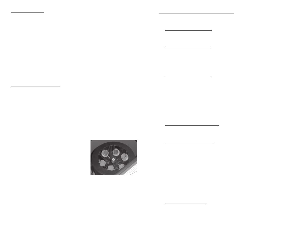
5. Place the test tube holders inside the rotor
and verify that they are seated properly.
6. Close the lid. Rotate the lid knob clock
wise to its complete stop position. The ‘LATCH’
in dicator light should be illuminated. If it is
not, make sure that the lid is latched properly.
The centrifuge will not run unless the lid is latched
properly and the ‘LATCH’ indicator light is illuminated.
7. Initiate a test run by pressing the ‘START’ button.
8. The ‘RUN’ indicator light will illuminate
9. The test tube carriers will slide up into the horizontal position (horizontal rotor
only) and the unit will accelerate to full speed.
10. Listen to the sound of the centrifuge. A smooth whirring sound should be heard.
If there are any loud or unusual sounds, stop the centrifuge by pressing the
‘OPEN/STOP’ button immediately and refer to the section on troubleshooting.
11. Push the ‘OPEN / STOP’ button. The ‘RUN’ indicator light should go out and the
motor should slow to a stop.
Page 4
Horizontal Rotor Shown
(cont.)
Care and Preventative Maintenance:
With proper care and maintenance your 642VFD centrifuge will provide years of
laboratory service. For proper care, the following steps should be taken:
1.
Provide Adequate Ventilation: For cooling purposes, the 642VFD draws in
ambient air through the air intake cover on the top of the lid and exhausts this
air in the rear of the base. The centrifuge should be placed on a hard smooth
surface for good air circulation.
2.
Always Spin Balanced Loads: Make certain that you are always spinning a
balanced load. The 642VFD has a unique counter balanced
motor mounting design which, along with it’s rubber suction feet, produces
excellent vibration dampening. However, out–of–balance loads may break
glass test tubes and may produce unsatisfactory separation results.
Proper load balancing will improve sample separation and extend the life of
the centrifuge. Refer to page 6 on balanced loads for additional information
on balancing the load.
3.
Keep the Tube Holders Clean: NOTE: Always follow the safety guidelines of
your laboratory to properly clean up and/or dispose of materials in the event
that a substance known to be potentially toxic, radioactive or contaminated
with a pathogenic microorganism is spilt in or on the centrifuge. Small
glass fragments left in the tube holder after a tube breakage may adhere to
the next test tube inserted in that holder. When this tube is handled, these
fragments may puncture protective gloves and lacerate the operator’s
fingers or hand. Remaining fragments may provide stress points on
subsequent tubes and result in additional breakage. If a tube breakage
occurs, carefully remove the tube holder. Properly dispose of the sample
and tube fragments and thoroughly clean both the inside and outside of the
tube holder. Insert a new tube cushion (if necessary) and replace the tube
holder in the rotor.
4.
Motor and Electrical Maintenance: The 642VFD uses a
brushless permanent split capacitor AC motor. It should not need servicing
for the life of the centrifuge. The electrical components are selected for high
reliability and should not need service.
5.
Keep the Rotor Chamber Clean: Every six months, or whenever there is a
tube breakage, (refer to the note in #3), it may be necessary to remove the
rotor and clean the rotor chamber. Follow the instructions on page 7 to
remove and reinstall the rotor.
CAUTION: Once the lid has been opened, unplug the line cord from the
electrical outlet to eliminate the risk of electric shock during cleaning.
The rotor chamber, rotor and accessories shall be thoroughly cleaned
using either isopropyl alcohol, soap and water, or bleach. The use of Fully/
Partially Halogenated Hydrocarbons, Ketones, Esters and all other
chemicals not prescribed by the manufacturer may cause damage to the
rotor and tube holders and shall not be used.
Apply cleaning solutions with a towel or cloth. Do not submerge the
centrifuge in water or other cleaning solutions as this will cause damage
and void your warranty!
6.
Tube Holder Replacement: It is recommended that the tube holders be
replaced after 24 months of use.
Page 9