Carlo Gavazzi RAD Series User Manual
Page 2
• Refer to the following table to change radar Set Values:
Factory Default Value
The device is set up in factory at the following default values:
1. Sensitivity:
10 (max level)
2. Relay hold time:
1 (min: 0.5 sec)
3. Uni-Bidirectional Detection Mode
Bi-directional (Uni-directional mode is
available only for RAD 02)
4. Immunity detection:
Immunity: OFF ; Quasi-Presence: OFF
5. Relay Status:
Passive
6. PIN security:
0000 - block disabled
(only for remote controller)
At the first start up, the device loads the default values.
Radar set value can be modified through the two buttons on the main PC board (On Board setting
procedure) or with the IR remote controller [optional] (IR remote controller setting).
The differences between on board settings procedure and IR controller settings procedure are only in
“Relay status”, “Restore” and the “PIN security code” features. “Restore” feature is only available by on
board push buttons while PIN security code function is available only by remote controller. “Relay status
feature” is partly available by on board push buttons and partly by remote controller.
Programming procedure
Warranty
Carlo Gavazzi guarantees radar device to be free of manufacturing defects for 2 Years from purchasing
date. The guarantee intervenes when the device presents a material defect. The faulty device can be
returned back to our factory and will be repaired free of charge. If the defect is due to an exceeding of
the permissible technical data, wrong wiring, not permissible changes in equipment by the user or a
faulty operation no guarantee is carried out.
DEFECT
PROBABLE CAUSE
RECOVERY ACTION
Door will not open or close when
radar sensor is activated.
The radar is not powered on
correctly.
The relay output wiring is not
correct.
Control electrical wiring diagram.
Door always remains open or
closed when radar sensor is
activated.
The radar always works with
OPEN or CLOSE features set on.
Set on AUTO feature by IR remote
controller.
Door is activated in reverse
mode.
Relay Status feature is set on
ACTIVE (NC) or PASSIVE (NO).
Set on AUTO feature by IR remote
controller.
Door constantly recycles (opens
and closes).
There is something moving in the
field detection area.
The radar sensor detects the door
motions.
Verify Immunity and Sensitivity set
values to increase radar motion
sensing feature.
Adjust vertical or lateral detection
angle and Sensing Field.
IR remote controller keyboard
does not work.
Remote control is lock.
The user PIN security code
entered with remote controller is
not correct.
Insert the correct user PIN
security code.
Refer to On Board Setting
Procedure and restore factory PIN
code.
Radar does not respond to the
Remote
Controller
Setting
Procedure.
Remote controller batteries are
run-down.
Remote Controller is not well
oriented toward radar sensor.
Check remote controller battery
insertion and voltage.
Orient the remote controller
correctly toward radar sensor.
Trouble Shooting
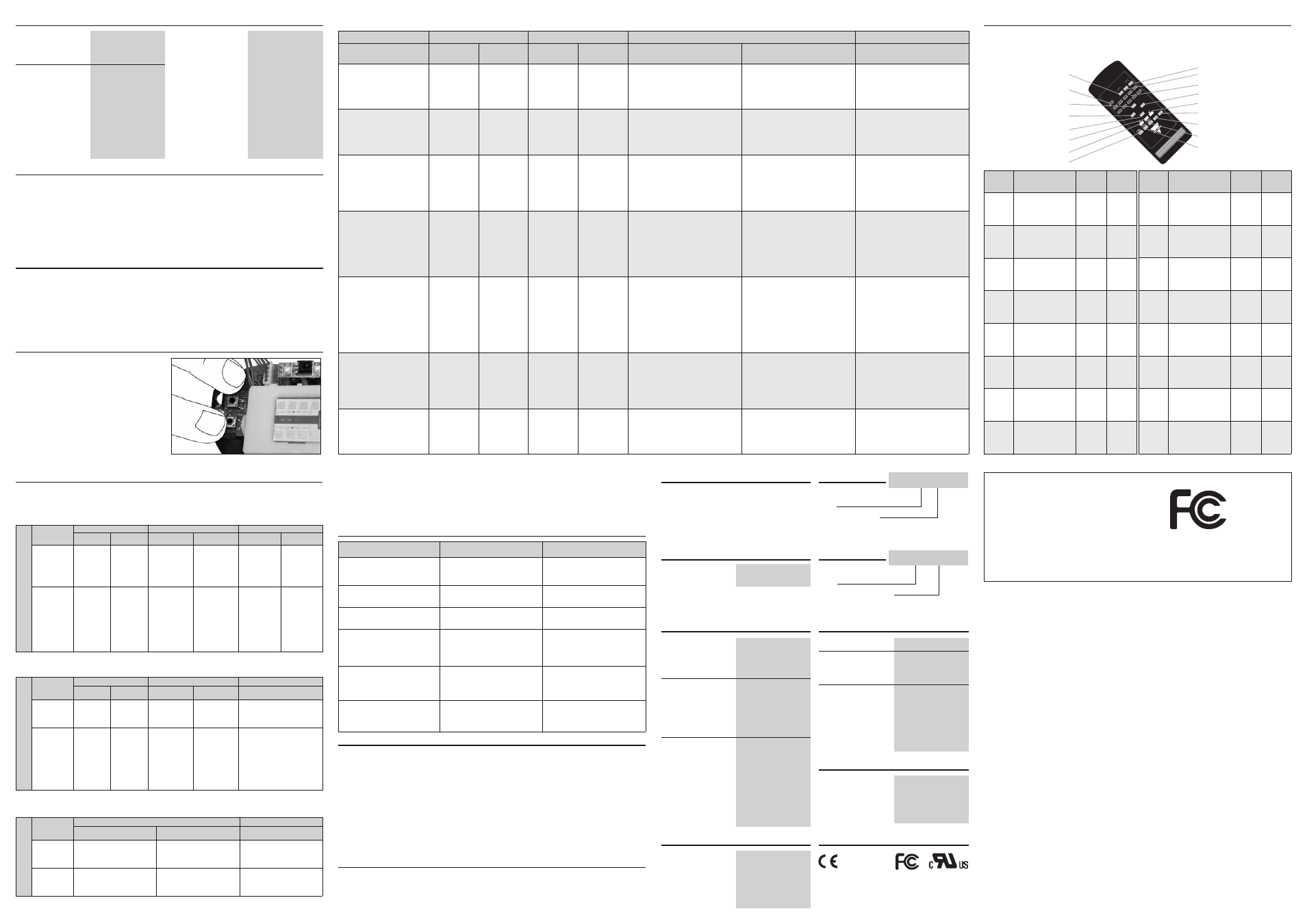
Please refer to the following tables in order to modify radar parameters setting with remote controller.
All changes made by remote controller, except (OPEN, CLOSE and AUTO), are stored into the radar memory
and reloaded during radar restart.
KEY
FUNCTION
RED
LED
RESPONSE
GREEN
LED
RESPONSE
1
0...9
Numerical keys
NONE
NONE
2
UNLOCK
If PIN is not equal to 0000
(factory default value),
press “UNLOCK” key
and insert the correct PIN
code to enable remote
controller setting.
See
next
table
NONE
3
LOCK
If PIN is not equal to 0000
(factory default value),
press “LOCK” key to
disable remote controller
setting.
See
next
table
NONE
4
TIME -
Press “TIME –” key to
decrease Hold Time set
value.
1…10
quick flash
NONE
5
TIME +
Press “TIME +” key to
increase Hold Time set
value.
1…10
quick flash
NONE
6
SENS -
Press “SENS -” key to
decrease Sensitivity set
value.
1…10
quick flash
NONE
7
SENS +
Press “SENS +” key to
increase
Sensitivity
value.
1…10
quick flash
NONE
8
PIN
Press “PIN” key to
change 4-number PIN
(It’s necessary to insert
the user PIN code if it’s
different from Factory
Default Value).
See
next
table
NONE
The remote controller device can be disabled inserting a four numbers PIN code therefore. All IR-remote
setting functions are available only if the correct PIN is inserted. The Security feature is activated only if
the PIN is different from 0000 (factory set value).
The next table shows the procedure to modify and set PIN Security code:
PIN Security code
F
O
U
R
P
IN
C
O
D
E
S
E
T
T
IN
G
ACTUAL
PIN VALUE
STEP 1
STEP 2
STEP 3
USER’S
ACTION
RED LED
ANSWER
USER’S
ACTION
RED LED
ANSWER
USER’S
ACTION
RED LED
ANSWER
Actual
PIN
code = 0000
(Factory
set
value)
Press once
“PIN” key.
Red LED will
flash once.
C o m p o s e
sequentially 0000
code with remote
c o n t r o l l e r
keyboard.
Red LED will
flash twice.
C o m p o s e
sequentially the
new XXXX PIN
value
with
remote controller
keyboard.
The red LED
will flash three
times
(The
new XXXX PIN
code now is
set).
Actual
PIN
code = xxxx
(User
set
value)
Press once
“PIN” key.
Red LED will
flash once.
C o m p o s e
sequentially the
actual
XXXX
code value with
r e m o t e
c o n t r o l l e r
keyboard.
Red LED will
flash twice if
PIN code is
OK:
get
to
Step 3.
No flash will
happen if PIN
code
is
not
correct: restart
from Step 1.
C o m p o s e
s e q u e n t i a l l y
the new YYYY
PIN value with
r e m o t e
c o n t r o l l e r
keyboard.
The red LED
will flash three
times
(The
new
YYYY
PIN code now
is set).
IR
R
E
M
O
T
E
C
O
N
T
R
O
L
L
E
R
U
N
L
O
C
K
ACTUAL
PIN VALUE
STEP 1
STEP 2
STEP 3
USER’S
ACTION
RED LED
ANSWER
USER’S
ACTION
RED LED
ANSWER
USER’S
ACTION
Actual
PIN
code = 0000
(Factory
set
value)
Not
available.
X
Not
available.
X
Not
available.
Actual
PIN
code = xxxx
(User
set
value)
Press once
“ U N L O C K ”
key.
Red LED will
flash once.
C o m p o s e
sequentially the
actual
XXXX
code value with
r e m o t e
c o n t r o l l e r
keyboard.
Red LED will
flash twice if PIN
code is OK: get
to Step 3.
No flash will
happen if PIN
code
is
not
correct: restart
from Step 1.
IR remote device keyboard is
activated and it’s possible to
use the device for setting
parameters.
IR
R
E
M
O
T
E
C
O
N
T
R
O
L
L
E
R
L
O
C
K
ACTUAL
PIN VALUE
STEP 1
STEP 2
USER’S
ACTION
RED LED ANSWER
USER’S
ACTION
Actual
PIN
code = 0000
(Factory
set
value)
Not
available.
X
Not
available.
Actual
PIN
code = xxxx
(User
set
value)
Press once “LOCK” key.
Red LED will flash once.
IR remote device keyboard is
disconnected and it’s not
possible to use the device for
setting parameters.
Notes:
• If no events happened per one minute, radar will restart automatically and reload the previous current
set values; Red LED will flash quickly per 1 second.
• If you have forgotten PIN XXXX code, it’s possible to reset the PIN factory value through the two
buttons on the main PC board: please refer to “RESTORE” feature of On Board setting Procedure.
IR remote controller setting procedure
The next tables show the procedure to UNLOCK and LOCK the IR remote controller keyboard.
Type
Detection mode
Ordering Key
Type selection
RAD 01
Detection Mode
Bidirectional*
01
Uni&Bi-directional*
02
* Bidirectional: to detect motion towards and
away from the sensor
Uni & Bidirectional: to detect motion towards
and/or away from the sensor.
Type
IR remote controller
Accessory
RAD 00 RC
Electrical data
Frequency emitted
(K-Band) 24.125GHz
Radiated power
< 16dBm EIRP
Rated supply voltage
12 – 24VAC ±10%
12 – 24VDC +30% / -
10%
Main frequency
50 to 60HZ
Power consumption
< 1W (VA)
Output Relay SPDT
Rated Voltage
30VAC/DC
Max switching current
1A (resistive load)
Max switching power
30W
(resistive load)
Hold time
0.5 – 9s (adjustable)
Environmental data
Temperature range
-20°C to +70°C
(-4°F to +158°F
)
Humidity
from 0% to 90%RH
Immunity
R&TTE 1999/5/EC
EMC 2004/108/EC
Max. mounting height
4m
(13.12ft
)
Protection degree
IP54
General data
Sensing field orientation double mechanical
adjustment,
lateral and vertical
Detection angle
Vertical
0° to 90° in 15° increments
Lateral
+/- 30° in 7.5° increments
Sensing field shape
bidirectional model
By Sensor module
orientation
Detecting area
(mounting height 2.2m (7.22ft))
Wide sensing field
4m (W) x 2m (D)
(13.12ft (W) x 6.56ft (D)
)
Narrow sensing field
2m (W) x 2.5m (D)
(6.56ft (W) x 8.20ft (D)
)
Detection mode
Only bidirectional
to detect motions towards
and away from sensor
Uni & bidirectional
to detect motions towards
or/and away from sensor
Motion detecting speed 0.05 - 1m/s (0.164 - 3.28fps)
(measured in the sensor axis)
Mechanical data
Housing Material
Polycarbonate
Dimensions WxHxD
118 x 80 x 53mm
(4.645 x 3.149 x 2.086inch.)
Weight
150g (5.29oz)
Cable length
2.5m (8.20ft)
Colour
Glossy/Translucid Black
Box Content
•
Motion Radar Sensor
•
Tie Clip for sensor fixing (RAD 01)
•
Connecting cable
• Screws and anchor fixing set
•
Instruction manual
Approvals
Manual Setting Device
By two buttons on main
PCB board.
Remote Setting Device
IR remote controller (optional)
Reset to factory set Value
1 - Restore PIN security code
(only by PCB buttons)
2 - Restore all factory values
Sensitivity
10 levels (1 to 10)
It allows increment or
decrement of detection
field.
Relay hold time
10 levels (0.5 to 9s)
It fixes the maintenance’s
time of the relay status.
Uni-bidirectional mode
It sets direction mode
detection (only for uni-
bidirectional device).
Immunity detection
“Quasi-presence”, Normal
mode, Increased Immunity
(Implemented by a digital filter)
Adjustment and Setting
It prevents some external
noise as objects carried
by wind, strong rain, etc.
Relay status
Active, Passive,
(only by PCB buttons)
It permits to fix the relay
status: normally open or
close.
Automatic mode/
(only by IR remote controller)
Permanently Open/Close. It permits to enable or disable
normal sensor detection and
set ON or OFF permanently
relay output.
AUTO / OPEN / CLOSE
Security code
4-digit PIN access code
(only by IR remote controller)
It permits to lock or unlock
optional remote controller
keyboard setting.
It is necessary to press simultaneously for 1
second the two PC-board buttons DEC(-) and
INC(+) to enter in programming procedure.
When the two buttons are released the Green LED
states permanently active (ON) so the device is
ready to be set.
Next setting action must be done in 20 seconds,
otherwise the device return in normal operation
mode and it’s necessary to restart.
On board setting procedure
KEY
FUNCTION
RED
LED
RESPONSE
GREEN
LED
RESPONSE
9
OPEN
Press “OPEN” key to
disable normal radar
detection functionality
and to set Relay Status
output always ACTIVE.
NONE
Always ON
10
CLOSE
Press “CLOSE” key to
disable normal radar
detection functionality
and to set Relay Status
output
always
NOT
ACTIVE.
NONE
A l w a y s
OFF
11
AUTO
Press “AUTO” key to
available normal radar
detection functionality.
NONE
NONE
12
IMM
Press “IMM” key once
to activate or twice to
disable
Immunity
feature.
1
quick
flash :ON
2
quick
flashes : OFF
NONE
13
FORWARD
Press “FORWARD” key
to
activate
uni-
directional
motion
detection towards the
sensor (available only
for RAD 02).
1
quick
flash
NONE
14
BACKWARD
Press
“BACKWARD”
key to activate uni-
directional
motion
detection away from the
sensor (available only
for RAD 02).
2
quick
flashes
NONE
15
BOTH
Press “BOTH” key to
activate bi-directional
motion
detection
towards or away from
the sensor (available
only for RAD 02).
3
quick
flashes
NONE
16
QP
Press “QP” key once to
activate or twice to
disable Quasi-Presence
feature.
1
quick
flash :ON
2
quick
flashes : OFF
NONE
STEPS
STEP 0
STEP 1
STEP 2
STEP 3
SETTING DESCRIPTION
USER’S
ACTION
GREEN LED
STATUS
USER’S
ACTION
RED LED
STATUS
USER’S
ACTION
RED LED STATUS
USER’S
ACTION
PROGRAMMING
PROCEDURE START UP
Press together
DEC & INC per 1
sec.
Green
LED
switch
on
permanently.
X
X
X
X
Press DEC & INC per 1 sec. to go to
Sensitivity (see Sensitivity STEP 1) or
wait 20 sec. to end setting procedure.
SENSITIVITY
X
X
Press together
DEC & INC per 1
sec.
Red LED will
flash once.
Press DEC or INC per 1 sec. to increase
or decrease Sensitivity current value.
Red LED flashes the number of the new
set value (1…10 quick flashes).
Return to Step 2 or press DEC & INC
per 1 sec. to go to Hold Time (see Hold
Time STEP 1) or wait 20 sec. to end
setting procedure.
HOLD TIME
X
X
Press together
DEC & INC per 1
sec.
Red LED will
flash twice.
Press DEC or INC per 1 sec. to increase
or decrease Hold Time current value
Red LED flashes the number of the new
set value (1…10 quick flashes).
Return to Step 2 or press DEC & INC
per 1 sec. to go to Detection Mode
(see Detection Mode STEP 1) or wait
20 sec. to end setting procedure.
DETECTION MODE
X
X
Press together
DEC & INC per 1
sec.
Red LED will
flash
three
times.
Feature available only for RAD 02
model.
• RAD 01: press DEC & INC per 1 sec.
to go to Immunity.
• RAD 02: press INC per 1 sec. to
change Detection Mode current
value.
Only for RAD 02 model:
1 quick Red LED flash: Toward;
2 quick Red LED flashes: Backward;
3 quick Red LED flashes: Toward and
Backward;
Return to Step 2 or press DEC & INC
per 1 sec. to go to Immunity (see
Immunity STEP 1) or wait 20 sec. to
end setting procedure.
IMMUNITY
X
X
Press together
DEC & INC per 1
sec.
Red LED will
flash four times.
Press INC per 1 sec. to change
Immunity current value.
1 quick flash: Immunity ON, QP OFF;
2 quick flashes: Immunity OFF, QP ON;
3 quick flashes: Immunity ON, QP ON;
4 quick flashes: Immunty OFF, QP OFF;
Return to Step 2 or press DEC & INC
per 1 sec. to go to Relay Status (see
Relay Status STEP 1) or wait 20 sec. to
end setting procedure.
RELAY STATUS
X
X
Press together
DEC & INC per 1
sec.
Red LED will
flash five times.
Press INC per 1 sec. to change Relays
Status current value
1 quick flash: Relay mode PASSIVE
(NO);
2 quick flashes: Relay mode ACTIVE
(NC);
Return to Step 2 or press DEC & INC
per 1 sec. to go to Restore (see Restore
STEP 1) or wait 20 sec. to end setting
procedure.
RESTORE
X
X
Press together
DEC & INC per 1
sec.
Red LED will
flash six times.
Press INC per 1 sec. to change Restore
current value.
1 quick flash: Restore PIN to 0000
2 quick flashes: Restore all to factory
default values.
Return to Step 2 or wait 20 sec. to end
setting procedure.
* Not available
RAD-M-ENG REV.00 02.06.08
1
F
2
3
4
5
6
7
S
E
N
S
-
8
TI
M
E
+
TI
M
E
-
9
S
E
N
S
+
0
O
P
E
N
C
LO
S
E
D
O
O
R
A
U
TO
IM
M
P
IN
Q
P
R
A
D
-0
0-
R
C
1
11
10
7
2
16
12
15
9
0*
5
13
6
4
8
3
14
0
06
68
82
2
Warnings
Warning: Changes or modifications made to this equipment not expressly approved by CARLO
GAVAZZI LOGISTICS may void the FCC authorization to operate this equipment.
This equipment has been tested and found to comply with the limits for a Class B digital device, pursuant
to Part 15 of the FCC Rules. These limits are designed to provide reasonable protection against harmful
interference in a residential installation. This equipment generates, uses and can radiate radio frequency
energy and, if not installed and used in accordance with the instructions, may cause harmful interference
to radio communications. However, there is no guarantee that interference will not occur in a particular
installation. If this equipment does cause harmful interference to radio or television reception, which can
be determined by turning the equipment OFF and ON, the user is encouraged to try to correct the
interference by one or more of the following measures:
•
Reorient or relocate the receiving antenna.
•
Increase the separation between the equipment and receiver.
•
Connect the equipment into an outlet on a circuit different from that to which the receiver is connected.
•
Consult the dealer or an experienced radio/TV technician for help.
Trade Name: Carlo Gavazzi Logistics S.p.A.
via Milano 13, I-20020 Lainate (MI)
Model No:
RAD01 / RAD01N
FCC
ID:
U7PRAD01
IC:
7118A-RAD01
Model No:
RAD02 / RAD02N
FCC
ID:
U7PRAD02
IC:
7118A-RAD02
This device complies with Part 15 of the FCC Rules and with RSS-210 of Industry Canada. Operation is subject to the following two conditions. (1) this device may not cause
harmful interference, and (2) this device must accept any interference received, including interference that may cause undesired operation.