Hydraulic cylinder mounting locations – Great Plains ADI445 Operator Manual User Manual
Page 15
13
Section 1 Assembly and Setup
5/11/05
Model 2250 Air Drill Implement 160-192M
Great Plains Mfg., Inc.
15149
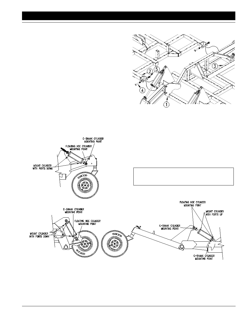
Hydraulic Cylinder Mounting Locations for Floating Hoe vs. Spring Shank
Figure 1-5
Dual Gauge Wheels
Wing Lift Assist
Connect frame section two (#2) to frame section three (#3)
using two pivot clevis bolts (#4) and 1” lock nuts (#5). Make
sure the pivot clevis bolt heads are oriented to the outside
of the clevis and seated next to the welded key stock on
the clevis. This will prevent rotation of the bolt in the clevis.
Repeat the above steps when joining frame section five to
frame section four.
Refer to Figure 1-4:
Move frame section one (#1) so that the pivot bushing end
is aligned with the clevis end of frame section two (#2). Be
sure frame section one is not confused with frame section
six. This can be avoided by making sure the lift assist arms
(#3) are positioned in the same direction as that of frame
sections three and four.
Connect frame section one (#1) to frame section two (#2)
using two pivot clevis bolts (#4), and 1” nuts (#5). Make
sure the pivot clevis bolt heads are oriented to the outside
of the clevis and seated next to the welded key stock on
the clevis.
Repeat the above steps when joining frame section 6 to
frame section 5.
The frame sections should now be assembled and still
supported by the shipping stands.
Hydraulic Cylinder Mounting Locations
Refer to Figure 1-5:
Frame Sections #1 & #2, and #5 & #6 Assembly
Figure 1-4
15110
NOTE: Failure to correctly mount cylinders could
cause damage to the implement voiding the warranty.