Wing caster wheel linkage assembly – Great Plains 7344 Series VII Field Cultivator-Floating Hitch Operator Manual User Manual
Page 22
Series VII 7332-7344 Field Cultivator, Floating Hitch 560-200M 2/17/2005
20
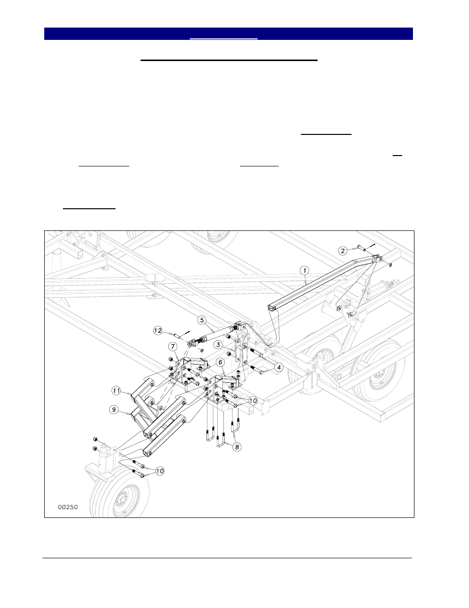
Wing Caster Wheel Linkage Assembly
Insert the wing level bar (1) through
the hole in the rocker fold bracket as shown in
Figure 8. Attach the wing level bar (1) to the
wheel bracket with a 1 x 3¼ clevis pin (2), 1”
flat washers, 1” machine washer and 3/16 x 2
cotter pin. Slide the leveling link (3) over the
leveling link mounting tube and attach with a 1
x 6 Gr.8 special thread hex bolt (4) and nylon
lock nut, do not torque. Bolt the gauge wheel
level bar (1) to the turnbuckle assembly (5)
through the leveling link (3) as shown. Use a
1 x 6 special thread hex bolt (4) and nylon lock
nut. Do not torgue as before.
U-bolt the gauge wheel arm mounts (6
& 7) to the brace bar with three ¾ x 3 x 5½ u-
bolts (8), lock washers and hex nuts. Insert the
bottom gauge wheel arm (9) and secure with 1
x 5½ Gr.8 special hex bolts w/zerks (10) and
nylon lock nuts, do not torque. Attach the top
gauge wheel arm (11) with the same 1 x 5½
GR8 special hex bolt and nylon lock nut, do
not torque. Connect the turnbuckle to the
bottom arm with a 1 x 2 3/8 usable clevis pin
(12), machine washer and 3/16 x 2 cotter pin.
See Caster Wheel Assembly, Section 3
Replacement Parts, for caster wheel exploded
diagram.
Figure 8