Quick setup guide for intelliag model nta – Great Plains DICKEY-john IntelliAg Quick Start User Manual
Page 4
Quick Setup Guide for IntelliAg Model NTA
11001-1460C-201107
©2011 DICKEY-john Corporation
Specifi cations subject to change without notice.
STEP 7: Ground Speed Calibration Setup
Press the Speed Set button
.
Enter desired values using Table H as reference.
Press the Work Screen button
when Ground Speed Calibration confi gura-
tions are complete to return to the Main Work screen.
1.
2.
3.
TABLE H:
Ground Speed
Setup
Default Value or
Value to Enter
Instructions/Defi nitions
Source
Digital Frequency
Select CAN Ground if radar is connected to ISO tractor cab har-
ness. Select Digital Frequency if radar or hall-effect is connected
to WSMT actuator harness.
Gspd Constant
3440 Pul/400 Ft
Input based on pulse count produced by the ground speed
sensor over 400’ distance. See Operator’s manual for calibration
instructions.
Shutoff Speed
0.01 mph
0.02 kph
Indicates the minium ground speed allowed before the system
shuts off all control channels.
Min Override
0.0 mph
0.0 kph
Minimum Override takes over when actual ground speed is below
the designated value. The control operates at this speed until
actual ground speed rises above the minimum override speed or
the actual speed drops below the shutoff speed.
Master Switch
Timeout
5 sec
Determines the length of time before the system disables the
operate function after ground speed is 0 if the master switch
remains in the ON position.
Ground Speed
Failure Alarm
Delay
5 sec
Set to desired number of seconds alarm sounds after the ground
speed is zero and seed fl ow continues. (monitor only)
Implement Lift
Enabled
Implement lift switch must be in the down position to operate.
STEP 8: Accessory Sensor Setup
Hopper Setup
Press the Module Confi guration button
.
Press the Hopper Assign button
.
Verify # of hoppers is correct or enter # of hoppers assigned.
Press the Hopper Set button
.
Enter desired values using Table I as reference.
RPM Sensor Setup
Press the RPM Module button
.
Enter # of RPM sensors, if required.
Press the RPM Setup button
.
Enter desired values using Table I as reference.
Pressure Sensor Setup
At the Module Confi guration screen, press the PSI Module button
.
Verify # of pressure sensors or enter the # of pressure sensors assigned.
Press the Pressure button
.
Enter desired values using Table I as reference.
For additional information regarding hopper level, RPM, and pressure sensor setup,
reference the Operator’s manual.
1.
2.
3.
4.
5.
6.
7.
8.
9.
9.
10.
11.
12.
4
TABLE I:
Accessory
Setup
Default Value or
Value to Enter
Instructions/Defi nitions
# of Hoppers
2
# of hopper sensors connected to each module. # of hopper data
items for each listed module and the Hopp #’s value will automati-
cally populate if Auto Confi g is used to confi gure installed sensors.
Hopper Logic
Level
Active Lo
Sets the active state to low signifying that an alarm is generated
if the sensor’s output is in a low state. Use this setting if the con-
nected sensor outputs a low condition when empty similar to the
DICKEY-john hopper sensor.
Hopper Alarm
Delay
5 sec
Controls the delay time between the detection of a high/low hop-
per alarm condition and the generation of the resulting alarm. The
value is entered in seconds.
Channel
(Hopper #1)
1
Assigns hopper sensor 1 to channel 1.
Channel
(Hopper #2)
2
Assigns hopper sensor 2 to channel 2.
# of RPMs
1
Number of RPM sensors connected to each module to monitor a
shaft/fan.
High Alarm
4100 RPM
Sets the RPM value at which a high RPM warning error is gener-
ated.
Low Alarm
2500 RPM
Sets the RPM value at which a low RPM warning error is gener-
ated.
High Alarm Delay
5 sec
Establishes the delay between the detection of a high RPM alarm
condition and the resulting alarm display (entered in seconds).
Low Alarm Delay
5 sec
Establishes the delay between the detection of a low RPM alarm
condition and the resulting alarm display (entered in seconds).
RPM Constant
3 pul
Number of pulses per sensor revolution.
RPM Filter
50%
Filters the signal out of the RPM sensor.
Disable Control on
Low Alarm
Disabled
Allows for disabling of all control channels if the RPM value of the
selected sensor falls below the low alarm level setting.
# of Pressure
Sensors
2
Number of pressure sensors connected to each module to monitor
pressure.
High Alarm
20 oz/in
2
Sets the pressure value at which a high pressure warning error is
generated (oz/in
2
).
Low Alarm
4 oz/in
2
Sets the pressure value at which a low pressure warning error is
generated (oz/in
2
).
High Alarm Delay
5 sec
Establishes the delay between the detection of a high pressure
alarm condition and the resulting alarm display (entered in
seconds).
Low Alarm Delay
5 sec
Establishes the delay between the detection of a low pressure
alarm condition and the resulting alarm display (entered in
seconds).
Pressure Filter
50
Filters the signal out of the pressure sensor.
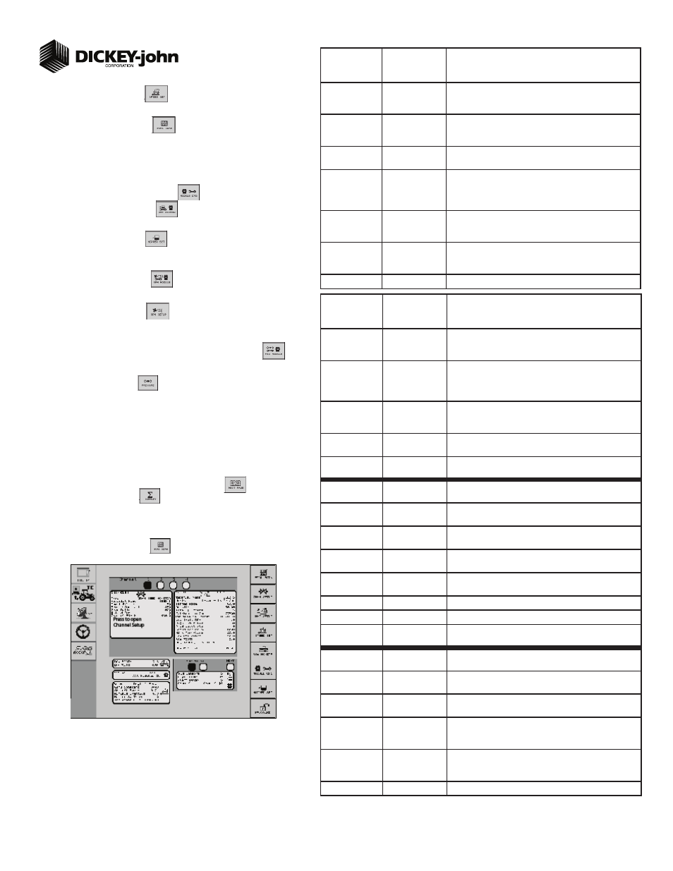
STEP 9: Summary Screen
The Summary screen provides an overview of setup constants for active control chan-
nels.
At the Main Work screen, press the Next Page button
.
Press the Summary button
To view specifi c control channel confi gurations, press the respective control chan-
nel box 1-4.
Press inside a yellow highlighted box to open a specifi c screen for editing.
Press the Work Screen button
to return to the Main Work screen.
1.
2.
3.
4.
5.
Summary Screen