Quick setup guide for intelliag model nta – Great Plains DICKEY-john IntelliAg Quick Start User Manual
Page 3
11001-1460C-201107
©2011 DICKEY-john Corporation
Specifi cations subject to change without notice.
Quick Setup Guide for IntelliAg Model NTA
STEP 6B: Channel Setup (Granular Fertilizer Monitor)
Channel 2 is generally used for granular fertilizer monitor setup.
At the Channel Setup screen, press the Next Channel button
to setup additional control channels.
Set channel 2 as granular fertilizer monitor.
Enter desired values using Table F as reference.
Continue to set up control channels 3 and 4, if required.
Press the Work Screen Button
when channel confi gu-
rations are complete to return to the Main Work screen.
Once a Control Channel has been established as Granular Fertil-
izer Monitor, any new materials established as granular fertilizer
monitor on the Material Setup screen will automatically be added
as optional materials for granular fertilizer monitor channels on
the Control Setup screen.
1.
2.
3.
4.
5.
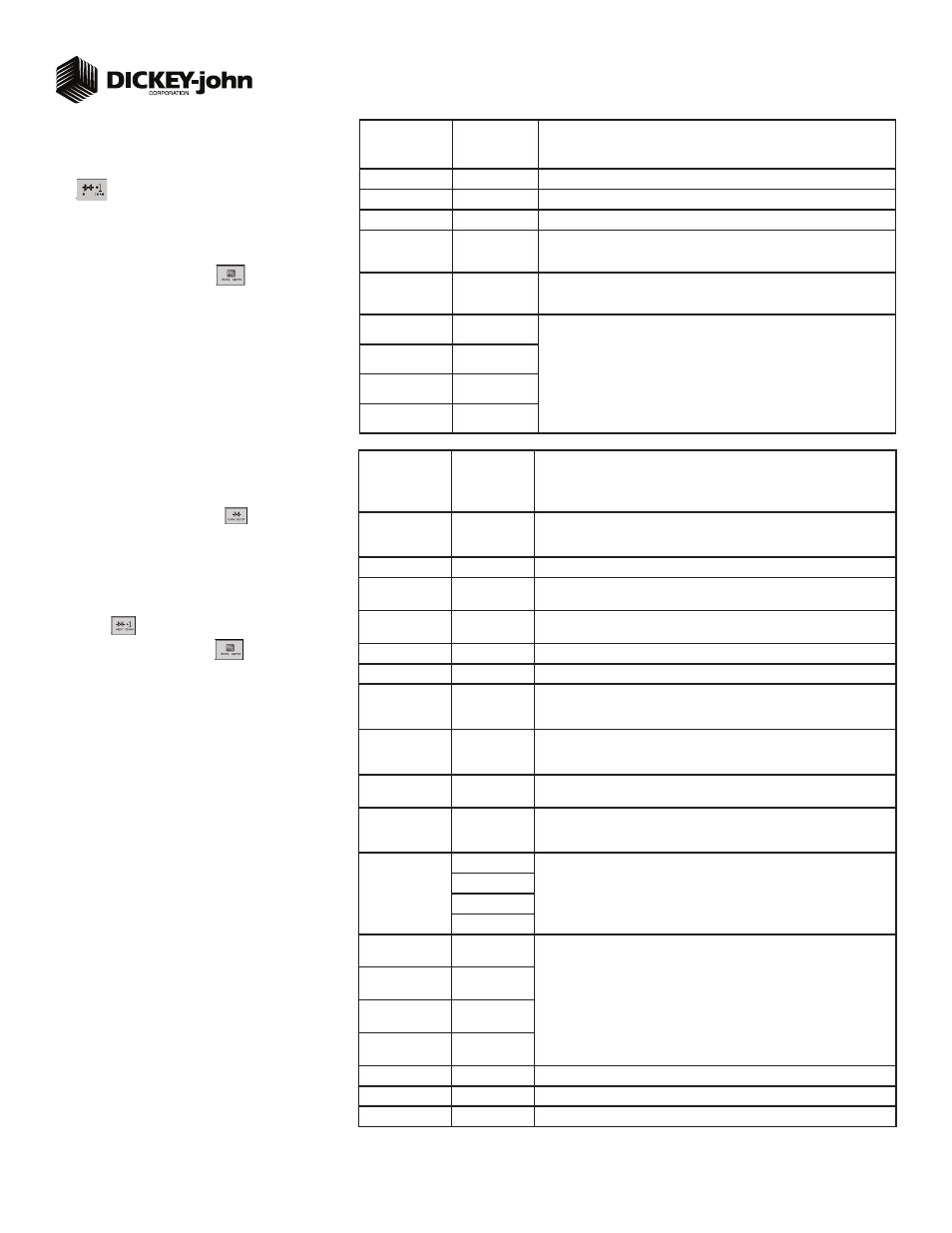
TABLE F:
Channel Setup
Gran Fert Mon
Default Value/
Value to Enter
Instructions/Defi nitions
Type
Gran Fert Monitor
Set desired Channel Type as Gran Fert Monitor.
Material Name
Fert 5
Displays only materials that have been confi gured for the channel type.
Input Filter
50
Feedback frequency fi lter for the control channel. DO NOT CHANGE.
Sensor Constant
360
Sensor Constant establishes the number of pulses for one revolution of the feedback
sensor. If a DICKEY-john application rate sensor is used, the value should be set to
360.0.
Gear Ratio
1.0
Specifys the actual ratio from the feedback sensor to the seed meter shaft RPM.
Number of revolutions the feedback sensor turns in relation to one revolution the seed
meter turns.
Channel Width
(35 ft. 55 row) 7.5”
416.5
Manual entry of the channel width for rows assigned to a specifi c channel. Width
calculation can be determined by # of seeder rows assigned to the channel multipled
by the row spacing.
Channel Width
(35 ft. 40 row) 10”
400
Channel Width
(30 ft. 48 row) 7.5”
364
Channel Width
(30 ft. 36 row) 10”
360
Step 6C only applies to those applications with a
variable rate kit option installed. Proceed to step 7 if
variable rate is not applicable.
STEP 6C: Channel Setup (Granular Seed & Fertilizer
Control)
Press the Channel Setup button
.
Select an available channel and set to either granular seed
control or granular fertilizer control.
Enter desired values using Table G as reference.
To set up additional control channels, press the Next Channel
button
.
Press the Work Screen button
when channel confi gu-
rations are complete to return to the main menu.
1.
2.
3.
4.
5.
TABLE G:
Channel Setup
Gran Seed &
Fert Setup
Default Value/
Value to Enter
Instructions/Defi nitions
Type
Gran Seed
Control/Gran Fert
Control
Set desired Channel Type as either Gran Seed Control or Gran Fertilizer Control.
Material Name
Seed 1/Fert 1
Displays only materials that have been confi gured for the channel type.
Control Mode
Auto
Calculates application rates based on ground speed and channel width under normal
operating conditions.
Drive Type
Zero Max
A Zero Max gear box controlled by a linear actuator for those applications with an
installed variable rate kit option.
Drive Frequency
40
The Hz frequency for the linear actuator specifi ed by the valve manufacturer.
Input Filter
50
Feedback frequency fi lter for the control channel. DO NOT CHANGE.
Sensor Constant
360
Sensor constant establishes the number of pulses for one revolution of the feedback
sensor. If a DICKEY-john application rate sensor is used, the value should be set to
360.0.
Gear Ratio
1.0
Specifys the actual ratio from the feedback sensor to the seed meter shaft RPM.
Number of revolutions the feedback sensor turns in relation to one revolution the seed
meter turns.
Grd Spd/Trans In
Ratio
45
Ratio between distance traveled to one revolution of the input to the Zero Max transmis-
sion. Ratio determines the input sprocket speed from the known ground speed.
Meter Gear Range
High/Low
Determined by the position of the interchangeable gears. High range used for larger
seeds and higher seeding rates. Low range used for smaller seeds and lower seeding
rates. Refer to Great Plain’s operator’s manual for recommended high/low setting.
# of Seed Rows
36 row
Entry of a specifi c number of seed rows to the control channel. Row assignment is given
a priority based on the channel and will be assigned sequentially thereafter. Channel 1
is always assigned to the fi rst set of rows. Channel 2 next set of rows, and so on.
40 row
48 row
55 row
Channel Width
(35 ft. 55 row) 7.5”
416.5
Manual entry of the implement width for rows assigned to a specifi c channel. Width
calculation can be determined by # of seeder rows assigned to the channel multipled by
the row spacing.
Channel Width
(35 ft. 40 row) 10”
400
Channel Width
(30 ft. 48 row) 7.5”
364
Channel Width
(30 ft. 36 row) 10”
360
Flush Enable
Disabled
Not applicable to ground drive systems.
Precharge Time
+ 0.0
Not applicable to ground drive systems.
Delay Time
- 0.0
Not applicable to ground drive systems.
3