Installing the transfer drive, Connecting the hydraulic circuits – Great Plains 3S-3000F Predelivery Manual User Manual
Page 12
10
Section 1 Assembly
3S-3000 Three-Section Folding Drill 195-144M
8/9/06
Great Plains Mfg., Inc.
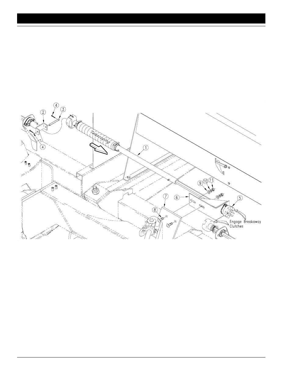
Installing the Transfer Drive
Refer to Figure 1-7:
Remove the transfer drive subassembly (#1) from the drill
seed box. The transfer drive assemblies to the right side of
the drill, and transfers the drive power to the center box as-
sembly. Assemble the U-joint end of the transfer drive as-
sembly (#1) to the U-joint yoke (#2) on the right wing box
with the 3/8" x 3 3/4" pin (#3) and 3/32" x 1" cotter pins
(#4). Clip the shipping wire, and telescope the end of the
drive assembly toward the break away-drive assembly at
the center of the drill. Engage the jaws of the break-away
clutches (#5), and fasten the bearing bracket (#6) to the
plate extending up from the right wing toolbar (#7). Use
the two 1/2" x 1 1/2" round head bolts (#8), 1/2" flat washer
#(9) 1/2" lockwashers (#10) and 1/2" nuts (#11). DO NOT
tighten the 1/2" bolts (#8) yet. The box lead must be ad-
justed before the drive assembly can be adjusted.
Connecting the Hydraulic Circuits
Refer to Figure 1-8:
Connect the 3/8" hydraulic hoses (#1) coming from the
back side of the wing pressure control valve to the base
end tees (#2) on the inner opener lift cylinder (#3) of each
wing frame. This is the hose which should extend beyond
the wing toolbar hose holder (#4) by 45" as assembled
from the factory. Connect the 3/8" hydraulic hoses (#5)
coming from the bottom of the wing pressure control valve,
to the tee (#6) at the jumper hose (#7) coming from the rod
end of the inner opener lift cylinder (#3)of each wing
frame. This is the hose which should extend beyond the
wing toolbar hose holder (#4) by 35" as assembled from
the factory. Disconnect the 3/8" hydraulic hoses (#1) &
(#5) where they tee together (#8) at the back of the
Transfer Drive Installation
Figure 1-7
15611