Assembly instructions, Marker assembly, Assembly – Great Plains 2SNG30 Assembly Instructions User Manual
Page 2
2
Two-Section, Hydraulic Folding Marker 113-329M
8/21/06
Great Plains Mfg., Inc.
Assembly
Assembly Instructions
Marker Assembly
1.
Lower drill into field position. Make sure the
assembly area is large enough for the drill
and markers (62 feet for a 30-foot drill or 50
feet for a 24-foot drill).
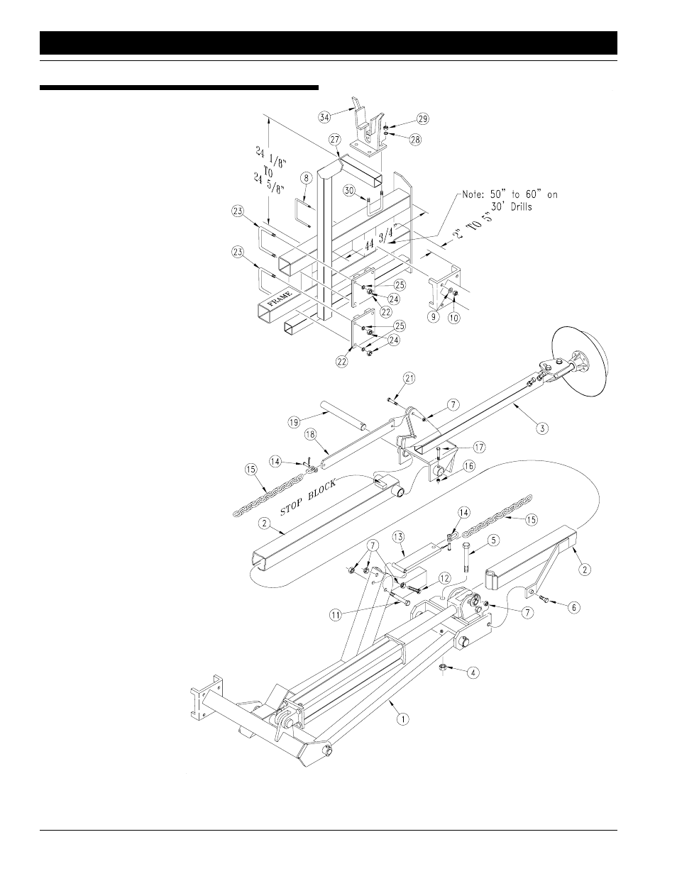
2.
Attach the marker first section with mount
(1) to the lower 3 1/2-inch tube of the
drill frame. Mount the 5/8-inch u-
bolts (8), lock washers (9) and hex
nuts (10).
NOTE: On 24-foot drills with dual gauge
wheels, markers may not be applicable
due to problems with clearance. If using
markers on a dual gauge wheel 24’ drill,
mounting the markers and the marker carrier
arm on the top frame tube will be acceptable. It
may also be necessary to move the gauge
wheel assembly towards the inside of the drill.
3.
Assemble the marker in a horizontal posi-
tion. Remove the port plugs in the hydraulic
cylinder then fold the first section and the lift
lug (1) to a horizontal position.
4.
With the stop block positioned on top of second section (2),
align the holes of the second section with the holes of the
first section (1) and bolt together with 5/8-by-5 1/2-inch bolt
(5), lock nut (4), 3/8-by-2-inch shear bolt (6) and lock nut (7).
5.
Place the third section (3) over the end of the second sec-
tion (2) and insert hinge pin (19) through the second and
third section pivot. Secure the hinge pin (19) with
1/4-by-2-inch bolt (17) and lock nut (16).
6.
Bolt the chain bar weldment (13) to the first section
(1) with 3/8-by-3 1/4-inch bolt (11) and lock nut
(7). The chain bar weldment (13) should pivot
freely on the 3/8-inch bolt (11). Bolt the
chain bar (18) to the third section (3)
with the
3/8-by-1 1/2-inch bolt (21) and lock nut
(7). The chain bar (18) should pivot
freely on the 3/8-inch bolt (21). Con-
nect the marker chain (15) between
the chain bar (18) and chain bar
weldment (13) with 5/16-inch utility clevis
(14). With the marker disk adjusted for
seeding width and disk touching the
ground, adjust chain length to remove
the slack. Adjustment should be made at
the utility clevis (14) nearest to the drill.
7.
Position the 3/8-inch stop bolt (12) and lock
nuts (7) in the lift arm (1) so the head of the stop bolt extends
as little as possible. After marker is folded, adjust stop bolt to
tighten chain.
8.
When mounting marker carrier (27), mount the marker car-
rier arm (27) to drill frame as noted in the illustration. Use the
clamp plates (22), 1/2-by-3 1/2-by-6 1/2-inch u-bolts (23),
lock washers (25), and hex nuts
(24). The carrier arm (27) should
be set 24 1/8 inches above
the drill frame.
NOTE: On 24-foot drills with
dual gauge wheels, mount carri-
er on top tube only. Discard one
clamp plate and its mounting
hardware. Set carrier arm (27) 32 5/8 inch-
es above drill frame.
NOTE: On bean machines, use 1/2-by-7 1/32-by-8-
inch u-bolts to mount larger clamp plates on top frame
tube.
Figure 1
Marker Assembly
11007