Great Plains 2S-2600 Installation Instructions User Manual
Page 5
2/22/2005
195-300M
Great Plains Mfg., Inc.
5
Installation Instructions
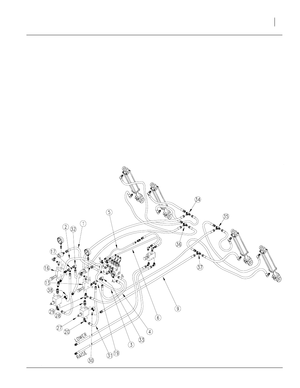
Refer to Figure 6
13. Install the LH Counterbalance valve (27) under the
LH reducing valve (13) using fitting (28) and tee (29)
from the kit. Be sure to connect port 2 on the CBV to
the T port on the reducing valve.
14. Connect supply hose (5) from the filter to the elbow
in port V1. Connect the return hose (6) to the elbow
in port V2.
15. Connect hose (1) from the RH reducing valve (16) P
port to the elbow on port A1. Connect hose (3) from
the LH reducing valve (13) P port to the elbow in
port A3.
16. Connect return hose (2) from the Tee in the bottom
of the RH reducing valve (16) to elbow in port B1.
Re-install return hose (4) from the Tee in the bottom
of the LH reducing valve (13) to the elbow on port
B3.
17. Install elbow (20), removed earlier and elbow
(30),from the kit, to ports 1 and 3 on
the LH CBV (27).
18. Connect the LH pilot line hose (31)
supplied with the kit, from elbow
(20) to Tee (19).
19. Connect elbows (32) and (33) from the
kit to Tees (17) and (19) on the back of
the reducing valves (13) and
(16).
20. Isolate the LH and the RH wing opener lift cylinders
on the drill by switching hoses at the T fittings (34),
(35), (36) and (37) at the rear of the mainframe. Con-
nect rod-end hoses to rod-end hoses and base end
hoses to base end hoses. Keep the LH wing and RH
wing separate. Connect hoses going forward from
the T's as follows:
• RH cylinders, base end Tee (34) to RH reducing
valve R port Tee (32).
• LH cylinders, base end Tee (35) to LH reducing
valve R port Tee (33).
• RH cylinders, rod end Tee (36) to RH CBV port 1
elbow (38).
• LH cylinders, rod end Tee (37) to LH CBV port 1
elbow (30).
21. This finishes the hose routing, tighten all fittings and
hardware.
Figure 6
Final Plumbing
22629