Dual flat fold marker hydraulic assembly, Assembly instructions – Great Plains 2600-2S Assembly Instructions User Manual
Page 3
3
2/28/2006
3000-3S and 2600-2S Marker Option 113-561M
Great Plains Mfg., Inc.
Assembly Instructions
3.
Route 252" long hose (#3) from the center of the drill to the
marker base end fitting. Route 272" long hose (#4) from the
center of the drill to the needle valve (#7) at the marker rod
end fitting. Route the marker hoses along the same path as
the opener lift hoses, allowing the same slack at the drill
toolbar pivots as the other hoses. Use the rubber hose pro-
tectors and hose clamp brackets which are already bolted to
your drill to secure the hoses in place. DO NOT alter the
routing or amount of hose slack of the existing hoses when
you loosen the clamp brackets to insert the marker hoses.
Tie the marker hoses to the opener lift hoses at the toolbar
vertical and horizontal pivots with cable ties (#16).
4.
Route the 348" long hoses (#5) down the center of the
tongue tube and connect them to the hoses (#3) and (#4)
with JIC adapters (#8) at the center of the center box sec-
tion. Make sure the hoses do not interfere with the center
clutch assembly.
5.
Bolt the selector valve (#10) to the valve mount bracket
(#17) on the tongue tube with the 3/8" x 3 1/4" long bolts
(#13), 3/8" lock washers (#14), and 3/8" hex nuts (#15). In-
stall the 1/2" FNPT adapters (#9) to the front and rear ports
of the selector valve (#10) and the 3/4" JIC elbows (#12) to
the cross ports. Assemble the 96" long 3/8" hoses (#11) to
the elbows (#12) on the selector valve.
6.
Connect the 348" long hoses (#5) to the rear adapters on
the selector valve (#10). Connect the long hoses from the
fold hydraulic circuit to the front adapters on the selector
valve. Secure the four 1/4" hoses going into the selector
valve to the top of the tongue with the hydraulic hose guards
(#18), the hose clamp brackets (#19), the 5/16" x 2 1/2" bolts
(#21), and 5/16" lock washers (#20). The 5/16" bolts screw
into the nuts which are welded to the top of the tongue tube.
7.
Tie the hoses down with plastic cable ties (#16) to prevent
pinching or kinking of hoses during the folding operation.
Tieing the hydraulic hoses to the marker mount tube as
shown in Figure 3 is the preferred way to assure that they
will flex properly and not get pinched by the marker first sec-
tion.
IMPORTANT: BEFORE FOLDING THE MARKER, BLEED ALL
THE AIR OUT OF THE HYDRAULIC SYSTEM.
8.
Bleed the marker hydraulic system as described in the drill
OPERATOR’S MANUAL.
9.
Set the marker raise and lower speeds as described in the
drill OPERATOR’S MANUAL.
Dual Flat Fold Marker
Hydraulic Assembly
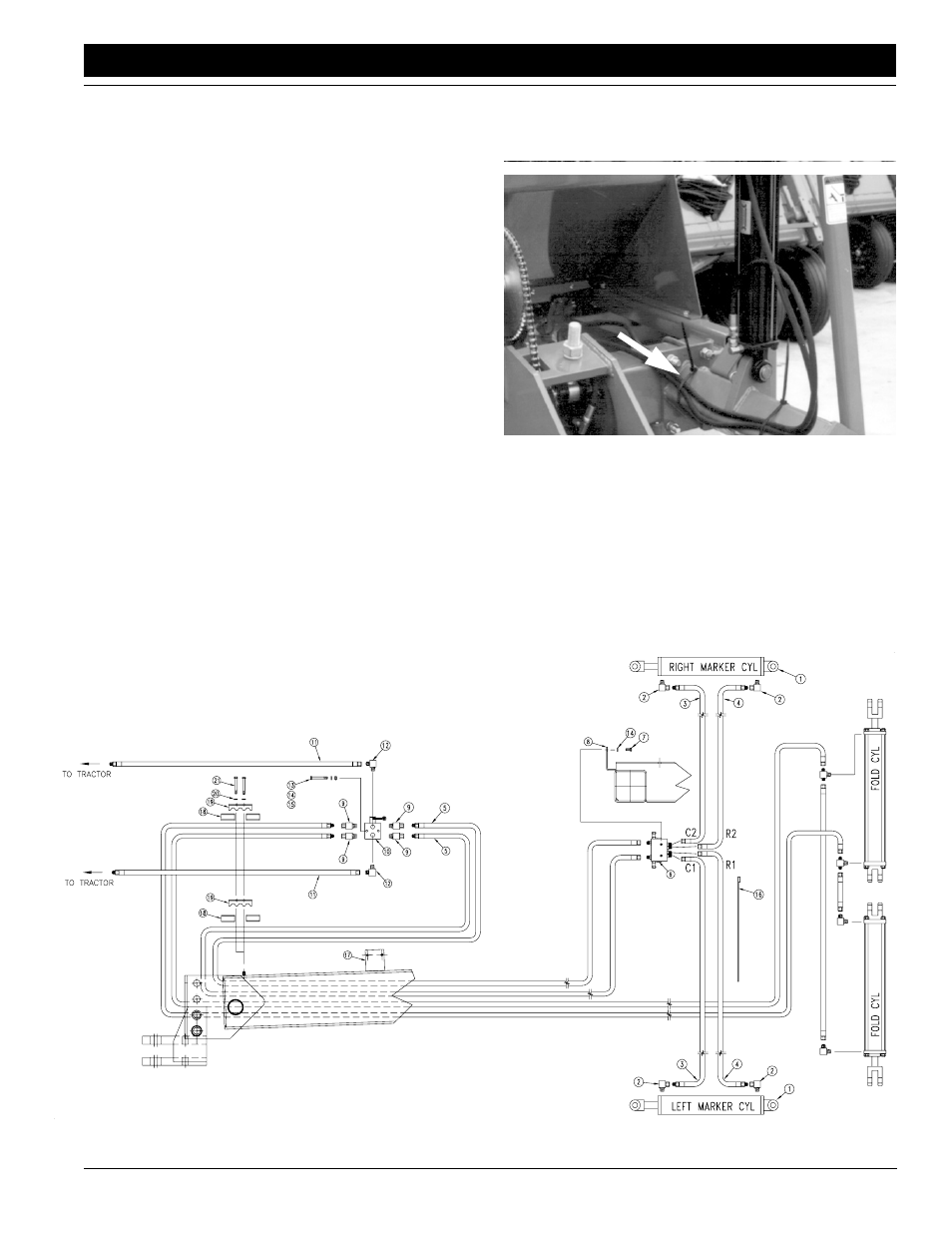
Refer to Figure 4:
1.
Assemble elbows (#2) to the hydraulic cylinder ports.
2.
Route 272" long hoses (#3) from the center of the drill to the
marker rod end fittings. Route 252" long hose (#4) from the
center of the drill to the marker base end fitting. Route the
marker hoses along the same path as the opener lift hoses,
Hydraulic Hose Routing at Marker Mount
Figure 3
15530
15686
Dual Marker Hydraulics
Figure 4